LEA-6 / NEO-6 - Hardware Integration Manual
GPS.G6-HW-09007-A Preliminary Design-in
Page 31 of 62
2.5.1 Passive antenna
A design using a passive antenna requires more attention regarding the layout of the RF section. Typically a
passive antenna is located near electronic components; therefore care should be taken to reduce electrical
‘noise’ that may interfere with the antenna performance. Passive antennas do not require a DC bias voltage and
can be directly connected to the RF input pin RF_IN. Sometimes, they may also need a passive matching network
to match the impedance to 50 Ohms.
Some passive antenna designs present a DC short to the RF input, when connected. If a system is
designed with antenna bias supply AND there is a chance of a passive antenna being connected to the
design, consider a short circuit protection.
All u-blox 6 receivers have a built-in LNA required for passive antennas.
Cosider optional ESD protection (see Section 3.3).
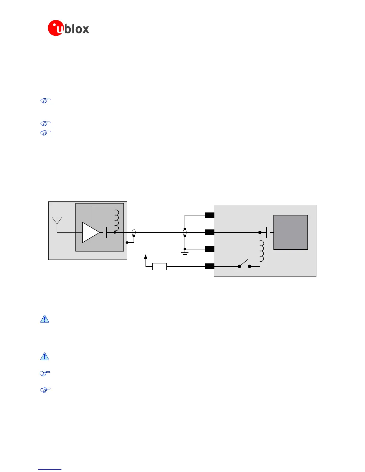
2.5.2 Active antenna (LEA-6)
Active antennas have an integrated low-noise amplifier. They can be directly connected to RF_IN. If an active
antenna is connected to RF_IN, the integrated low-noise amplifier of the antenna needs to be supplied with the
correct voltage through pin V_ANT. Usually, the supply voltage is fed to the antenna through the coaxial RF
cable. Active antennas require a power supply that will contribute to the total GPS system power consumption
budget with additional 5 to 20 mA typically. Inside the antenna, the DC component on the inner conductor will
be separated from the RF signal and routed to the supply pin of the LNA (see Figure 24).
Figure 24: Active antenna biasing (for exact pin orientation see data sheet)
Generally an active antenna is easier to integrate into a system design, as it is less sensitive to jamming compared
to a passive antenna. But an active antenna must also be placed far from any noise sources to have good
performance.
Antennas should only be connected to the receiver when the receiver is not powered. Do not
connect or disconnect the Antenna when the u-blox 6 receiver is running as the receiver
calibrates the noise floor on power-up. Connecting the antenna after power-up can result in
prolonged acquisition time.
Never feed supply voltage into RF_IN. Always feed via V_ANT.
To test GPS signal reacquisition, it is recommended to physically block the signal to the antenna, rather
than disconnecting and reconnecting the receiver.
Consider optional ESD protection, see section 3.3 for more information.

 Loading...

