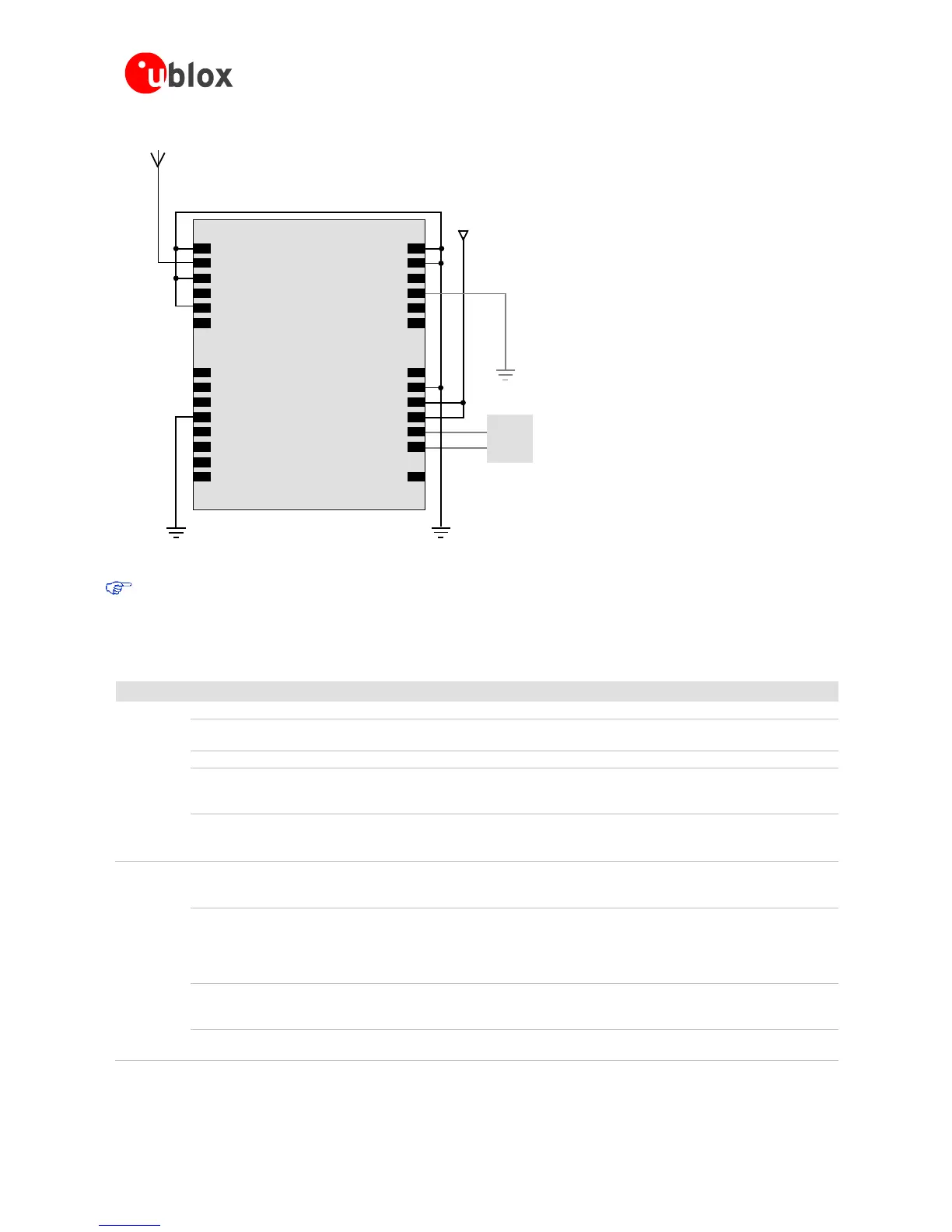
Figure 12: Passive antenna design for LEA-6 receivers not using USB port and not using backup battery
For best performance with passive antenna designs use an external LNA to increase the sensitivity up to
2dB.
2.2.2 Pin description for antenna designs (LEA-6)
Function PIN No I/O Description Remarks
Power VCC 6 I Supply Voltage Provide clean and stable supply.
GND 7, 13-15,
17
I Ground Assure a good GND connection to all GND pins of the module,
preferably with a large ground.
VCC_OUT 8 O Connected to VCC. Leave open if not used.
V_BCKP 11 I Backup voltage
supply
It’s recommended to connect a backup battery to V_BCKP in order
to enable Warm and Hot Start features on the receivers. Otherwise
connect to GND.
VDDUSB 24 I USB Power
Supply
To use the USB interface connect this pin to 3.0 – 3.6V derived from
VBUS.
If no USB serial port used connect to GND.
Antenna RF_IN 16 I GPS/GALILEO
signal input
from antenna
Use a controlled impedance transmission line of 50 Ohm to connect
to RF_IN.
Don’t supply DC through this pin. Use V_ANT pin to supply power.
VCC_RF 18 O Output Voltage
RF section
Can be used to power an external active antenna (VCC_RF
connected to V_ANT with 10R). The max power consumption of
the Antenna must not exceed the datasheet specification of the
module.
Leave open if not used.
V_ANT 19 I Antenna Bias
voltage
Connect to GND (or leave open) if Passive Antenna is used. If an
active Antenna is used, add a 10R resistor in front of V_ANT input
to the Antenna Bias Voltage or VCC_RF
AADET_N 20 I Active Antenna
Detect
Input pin for optional antenna supervisor circuitry. Leave open if not
used.

 Loading...

