LEA-6 / NEO-6 - Hardware Integration Manual
GPS.G6-HW-09007-A Preliminary Appendix
Page 54 of 62
Pin
LEA-4A/LEA-4S LEA-6A/LEA-6S Remarks for Migration
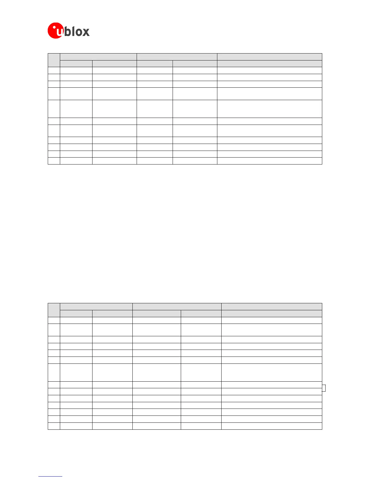
Pin Name Typical Assignment Pin Name Typical Assignment
18 VCC_RF VCC - 0.1V VCC_RF VCC - 0.1V No difference
19 V_ANT 3.0V - 5.0V V_ANT 2.7V -5.5V No difference
20 AADET_N NC (1.8 to 5.0V) AADET_N NC
21 GPSMODE5
NC (GND or
VDD18OUT)
NC NC
22
GPSMODE2
GPSMODE2
3
NC (GND or
VDD18OUT)
NC NC
23 GPSMODE7 NC (1.8 to 5.0V) NC NC
24 VDDUSB 3.0 –3.6V/ GND VDDUSB
Connected to GND
or VDD_USB
Do not leave open. (VDD_USB is 3.3V regulated
power supply from VBUS.)
25 USB_DM VDDUSB I/O USB_DM NC
No difference
26 USB_DP VDDUSB I/O USB_DP NC No difference
27 EXTINT0 NC (1.8 to 5.0V) EXTINT0 NC Max. 3.6V
28 TIMEPULSE VDDIO level output TIMEPULSE Output
Table 15: Pin-out comparison LEA-4A/LEA-4S vs. LEA-6A/LEA-6S
B.4.2 Migration from LEA-5 to LEA-6
For u-blox6 only the Input Voltage thresholds on the pins RXD1 and EXTINT0 have changed.
Be aware, that with u-blox 6 there is no LEA anymore, which supports SPI interface. For SPI consider NEO-6 form
factor.
B.5 Migration of NEO modules
B.5.1 Migration from NEO-4S to NEO-6
See also the migration Table in the u-blox 5 Hardware Integration Manual.
For u-blox6 the Input Voltage thresholds on the pins RXD1 and EXTINT0 have changed.
The Safeboot functionality is inverted compared to Antaris receivers.
Also check your power supply requirements with the datasheet (for VCC and VBCKP).
Also check the setting of the configuration pins.
The pin-outs of NEO-4S and NEO-6M/NEO-6Q differ slightly. Table 16 compares the modules and highlights the
differences to be considered.
Pin
NEO-4S NEO-6Q/NEO-6M Remarks for Migration
Pin Name Typ. Assignment Pin Name Typ. Assignment
1 BOOT_INT NC Reserved NC do not drive low.
2 SELECT
VDDIO level I/O;
not connected
SS_N NC
3 TIMEPULSE VDDIO level I/O TIMEPULSE Output
4 EXTINT0 NC EXTINT0 NC
5 USB_DM NC USB_DM NC No difference
6 USB_DP NC USB_DP NC No difference
7 VDDUSB
Connected to
GND or
VDD_USB
VDDUSB
Connected to
GND or
VDD_USB
Do not leave open. (VDD_USB is 3.3V regulated
power supply from VBUS.)
8 Reserved NC Reserved NC Pins 8 and 9 must be connected.
9 VCC_RF VCC-0.1V VCC_RF VCC-0.1V No difference
10 GND GND GND GND No difference
11 RF_IN RF_IN RF_IN RF_IN No difference
12 GND GND GND GND No difference
13 GND GND GND GND No difference
14 MOSI NC MOSI/CFG_COM0 NC
The function of the CFG pin has changed. See

 Loading...

