EasyManuals Logo

u-blox LEA-6 Series Hardware Integration Manual

u-blox LEA-6 Series
62 pages
To Next Page IconTo Next Page
To Previous Page IconTo Previous Page
Page #16 background imageLoading...
Page #16 background image
LEA-6 / NEO-6 - Hardware Integration Manual
GPS.G6-HW-09007-A Preliminary Hardware description
Page 16 of 62
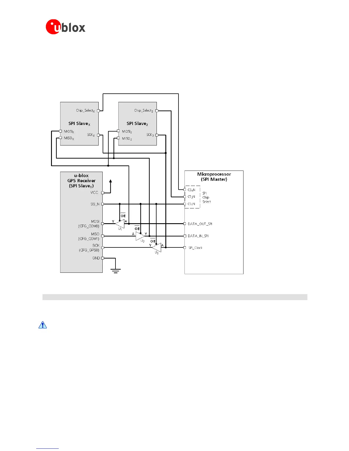
1.6.4.3 Pin configuration with module as one of several slaves
The buffers enabled by the CS_N signal make sure that the GPS receiver starts up with a known defined
configuration, since the SPI pins (MOSI, MISO and SCK) are at start up also configuration pins.
Figure 9: Diagram of SPI Pin Configuration
Component Description Model Supplier
U
1
– U
3
Buffer NC7SZ125 Fairchild
Figure 10: Recommended components for SPI pin configuration
Use same power voltage to supply U
1
– U
3
and VCC.
Downloaded from DatasheetLib.com - datasheet search engine

Table of Contents

Other manuals for u-blox LEA-6 Series

Questions and Answers:

Question and Answer IconNeed help?

Do you have a question about the u-blox LEA-6 Series and is the answer not in the manual?

u-blox LEA-6 Series Specifications

General IconGeneral
Brandu-blox
ModelLEA-6 Series
CategoryGPS
LanguageEnglish

Related product manuals