9
8. Allow at least 1-1/2 inches clearance behind the unit for electri-
cal and water supply connections.
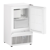
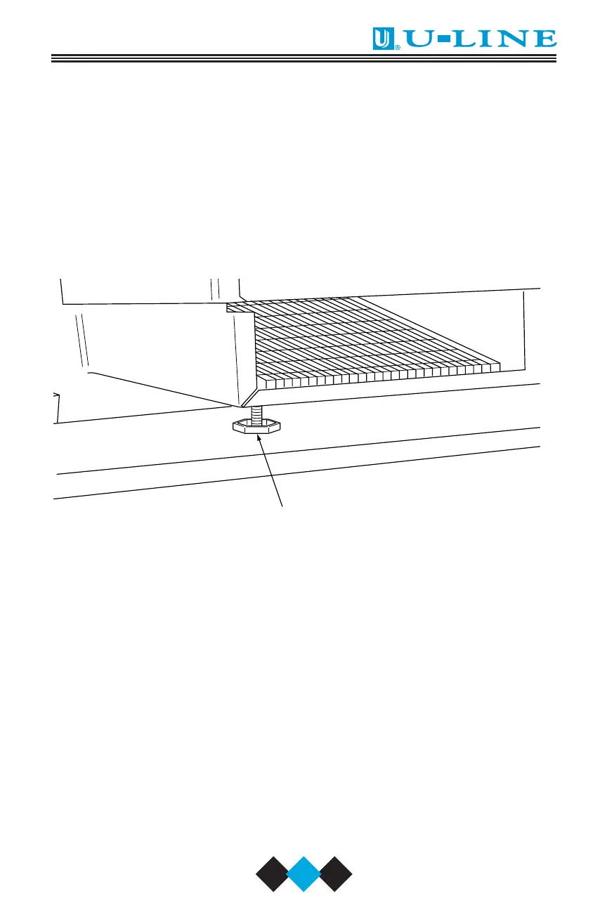
LEVELING THE UNIT
It is important that the unit, primarily the ice maker assembly, is level.
All 75 and 15 Series units are equipped with adjustable feet for level-
ing and height adjustment (see Figure 9). All other units have rubber
feet.
Figure 9
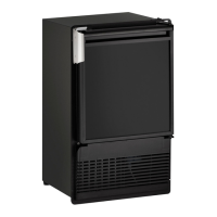
GRILLE INSTALLATION
NOTE
Model SP18 Icemakers come with the grille already
installed.
29 AND 75 MODELS
1. With a standard blade screwdriver (or 1/4” nutdriver), remove
the screw needed to attach the grille (see Figure 10).
2. Remove the control knob by pulling it toward you.
3. Carefully remove the grille from inside the unit. A small screw hole
is located toward the top of the middle recessed section of the
grille.
UL105TURN FOOT TO ADJUST
Users Manual 41923 9/2/03 3:44 PM Page 9
 Loading...