USER GUIDE
Control Operation
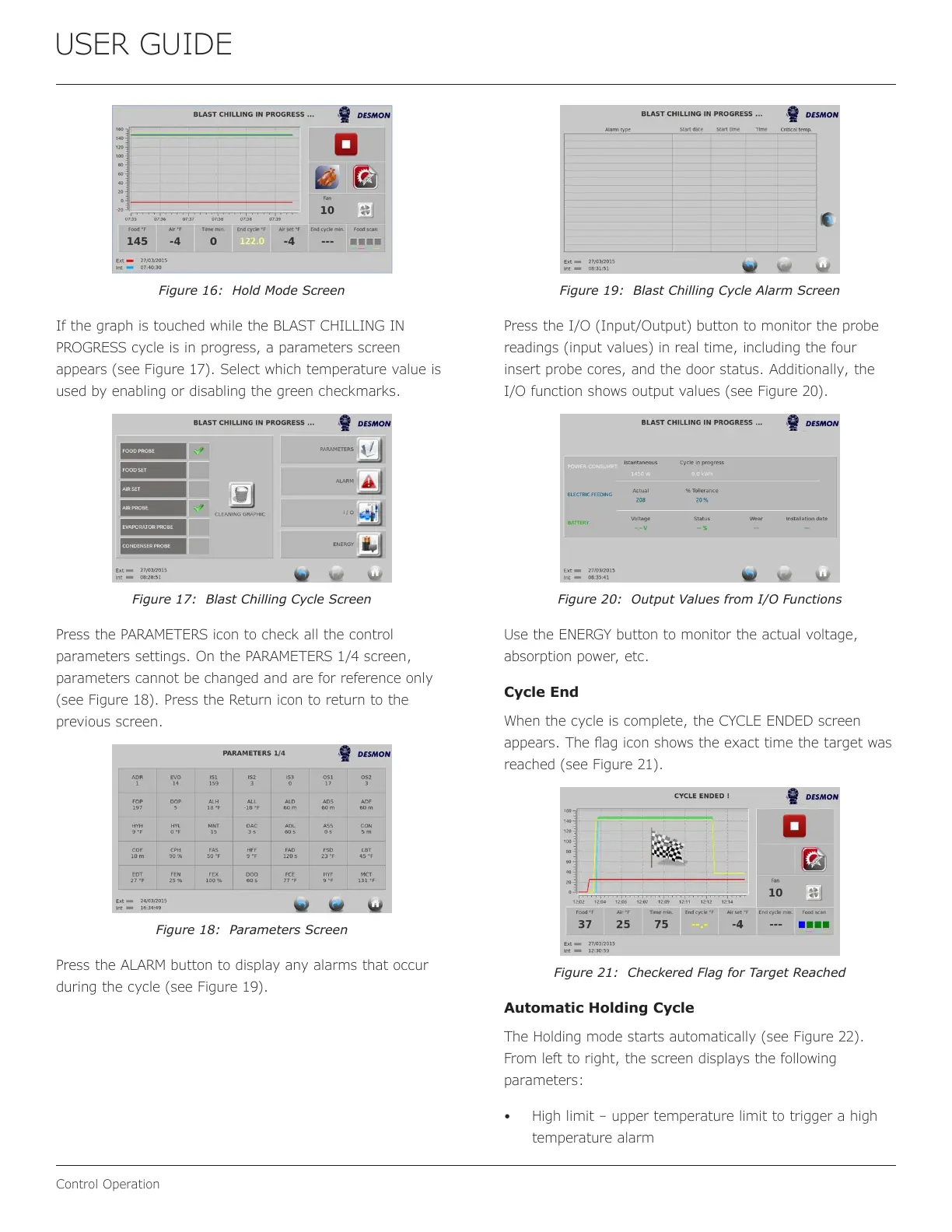
Figure 16: Hold Mode Screen
If the graph is touched while the BLAST CHILLING IN
PROGRESS cycle is in progress, a parameters screen
appears (see Figure 17). Select which temperature value is
used by enabling or disabling the green checkmarks.
Figure 17: Blast Chilling Cycle Screen
Press the PARAMETERS icon to check all the control
parameters settings. On the PARAMETERS 1/4 screen,
parameters cannot be changed and are for reference only
(see Figure 18). Press the Return icon to return to the
previous screen.
Figure 18: Parameters Screen
Press the ALARM button to display any alarms that occur
during the cycle (see Figure 19).
Figure 19: Blast Chilling Cycle Alarm Screen
Press the I/O (Input/Output) button to monitor the probe
readings (input values) in real time, including the four
insert probe cores, and the door status. Additionally, the
I/O function shows output values (see Figure 20).
Figure 20: Output Values from I/O Functions
Use the ENERGY button to monitor the actual voltage,
absorption power, etc.
Cycle End
When the cycle is complete, the CYCLE ENDED screen
appears. The ag icon shows the exact time the target was
reached (see Figure 21).
Figure 21: Checkered Flag for Target Reached
Automatic Holding Cycle
The Holding mode starts automatically (see Figure 22).
From left to right, the screen displays the following
parameters:
• High limit – upper temperature limit to trigger a high
temperature alarm
22
 Loading...