USER GUIDE
Troubleshooting
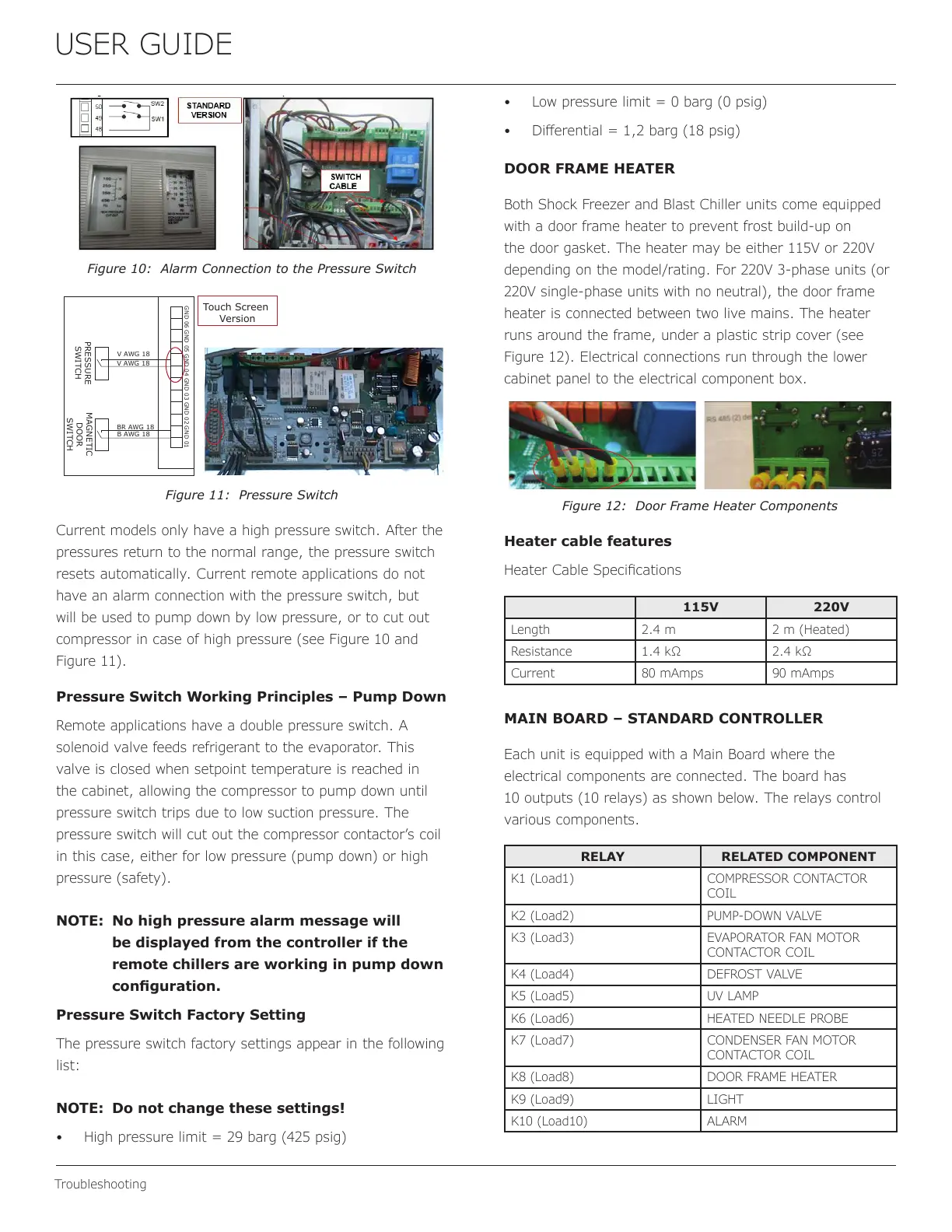
Figure 10: Alarm Connection to the Pressure Switch
V AWG 18
V AWG 18
BR AWG 18
B AWG 18
GND 04GND 06 GND 03 GND 01GND 02GND 05
PRESSURE
SWITCH
MAGNETIC
DOOR
SWITCH
Touch Screen
Version
Figure 11: Pressure Switch
Current models only have a high pressure switch. After the
pressures return to the normal range, the pressure switch
resets automatically. Current remote applications do not
have an alarm connection with the pressure switch, but
will be used to pump down by low pressure, or to cut out
compressor in case of high pressure (see Figure 10 and
Figure 11).
Pressure Switch Working Principles – Pump Down
Remote applications have a double pressure switch. A
solenoid valve feeds refrigerant to the evaporator. This
valve is closed when setpoint temperature is reached in
the cabinet, allowing the compressor to pump down until
pressure switch trips due to low suction pressure. The
pressure switch will cut out the compressor contactor’s coil
in this case, either for low pressure (pump down) or high
pressure (safety).
NOTE: No high pressure alarm message will
be displayed from the controller if the
remote chillers are working in pump down
conguration.
Pressure Switch Factory Setting
The pressure switch factory settings appear in the following
list:
NOTE: Do not change these settings!
• High pressure limit = 29 barg (425 psig)
• Low pressure limit = 0 barg (0 psig)
• Dierential = 1,2 barg (18 psig)
DOOR FRAME HEATER
Both Shock Freezer and Blast Chiller units come equipped
with a door frame heater to prevent frost build-up on
the door gasket. The heater may be either 115V or 220V
depending on the model/rating. For 220V 3-phase units (or
220V single-phase units with no neutral), the door frame
heater is connected between two live mains. The heater
runs around the frame, under a plastic strip cover (see
Figure 12). Electrical connections run through the lower
cabinet panel to the electrical component box.
Figure 12: Door Frame Heater Components
Heater cable features
Heater Cable Specications
115V 220V
Length 2.4 m 2 m (Heated)
Resistance 1.4 kΩ 2.4 kΩ
Current 80 mAmps 90 mAmps
MAIN BOARD – STANDARD CONTROLLER
Each unit is equipped with a Main Board where the
electrical components are connected. The board has
10 outputs (10 relays) as shown below. The relays control
various components.
RELAY RELATED COMPONENT
K1 (Load1) COMPRESSOR CONTACTOR
COIL
K2 (Load2) PUMP-DOWN VALVE
K3 (Load3) EVAPORATOR FAN MOTOR
CONTACTOR COIL
K4 (Load4) DEFROST VALVE
K5 (Load5) UV LAMP
K6 (Load6) HEATED NEEDLE PROBE
K7 (Load7) CONDENSER FAN MOTOR
CONTACTOR COIL
K8 (Load8) DOOR FRAME HEATER
K9 (Load9) LIGHT
K10 (Load10) ALARM
37
 Loading...