USER GUIDE
Troubleshooting
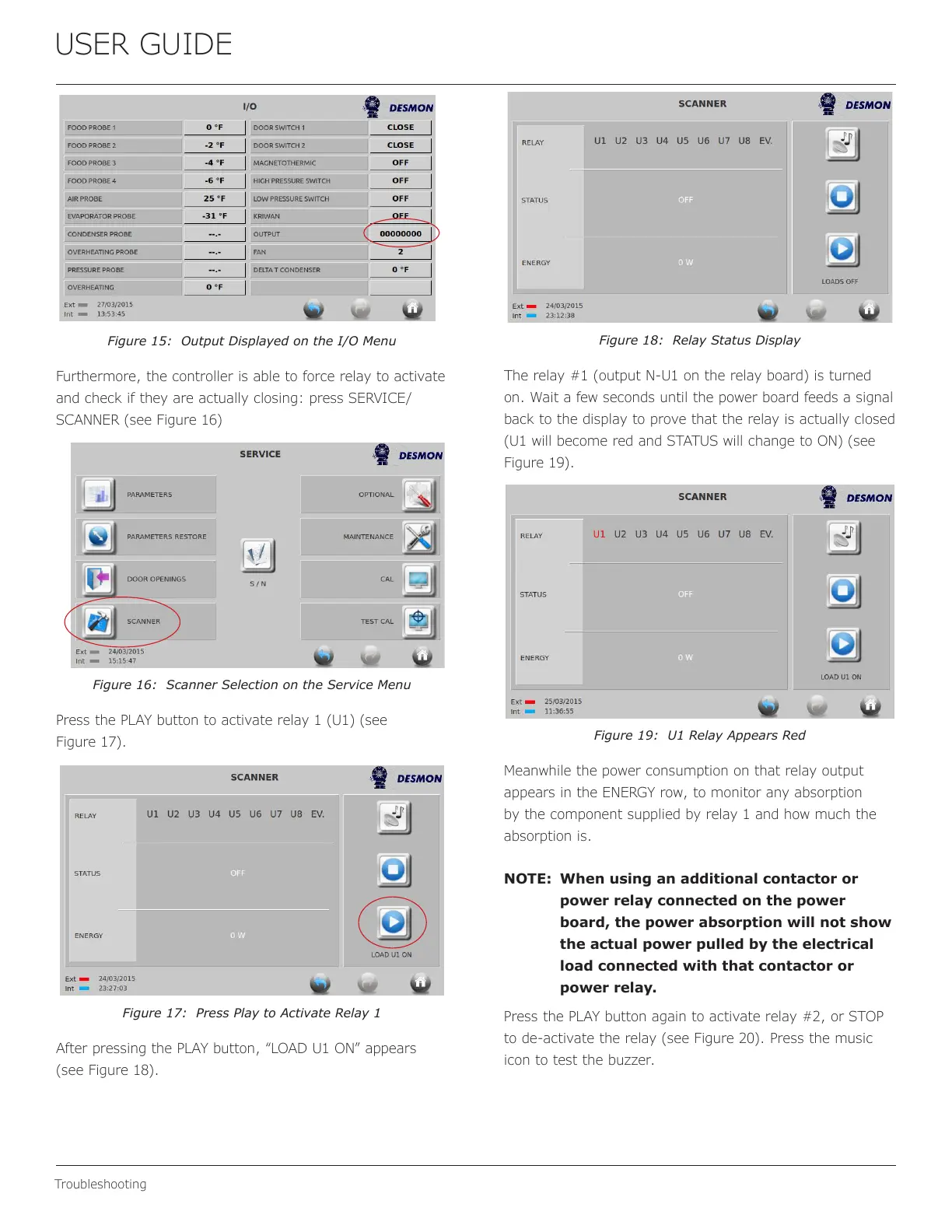
Figure 15: Output Displayed on the I/O Menu
Furthermore, the controller is able to force relay to activate
and check if they are actually closing: press SERVICE/
SCANNER (see Figure 16)
Figure 16: Scanner Selection on the Service Menu
Press the PLAY button to activate relay 1 (U1) (see
Figure 17).
Figure 17: Press Play to Activate Relay 1
After pressing the PLAY button, “LOAD U1 ON” appears
(see Figure 18).
Figure 18: Relay Status Display
The relay #1 (output N-U1 on the relay board) is turned
on. Wait a few seconds until the power board feeds a signal
back to the display to prove that the relay is actually closed
(U1 will become red and STATUS will change to ON) (see
Figure 19).
Figure 19: U1 Relay Appears Red
Meanwhile the power consumption on that relay output
appears in the ENERGY row, to monitor any absorption
by the component supplied by relay 1 and how much the
absorption is.
NOTE: When using an additional contactor or
power relay connected on the power
board, the power absorption will not show
the actual power pulled by the electrical
load connected with that contactor or
power relay.
Press the PLAY button again to activate relay #2, or STOP
to de-activate the relay (see Figure 20). Press the music
icon to test the buzzer.
39
 Loading...