USER GUIDE
System Diagnosis Guide
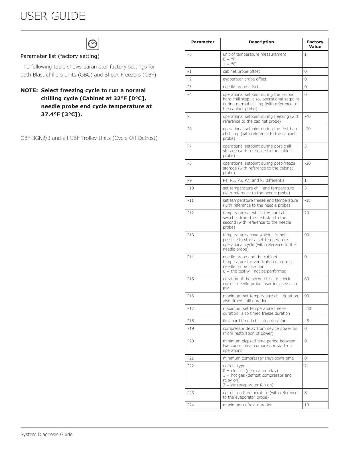
Parameter list (factory setting)
The following table shows parameter factory settings for
both Blast chillers units (GBC) and Shock Freezers (GBF).
NOTE: Select freezing cycle to run a normal
chilling cycle (Cabinet at 32°F [0°C],
needle probe end cycle temperature at
37.4°F [3°C]).
GBF-3GN2/3 and all GBF Trolley Units (Cycle O Defrost)
Parameter Description Factory
Value
P0 unit of temperature measurement
0 = °F
1 = °C
1
P1 cabinet probe oset 0
P2 evaporator probe oset 0
P3 needle probe oset 0
P4 operational setpoint during the second
hard chill step; also, operational setpoint
during normal chilling (with reference to
the cabinet probe)
0
P5 operational setpoint during freezing (with
reference to the cabinet probe)
-40
P6 operational setpoint during the rst hard
chill step (with reference to the cabinet
probe)
-20
P7 operational setpoint during post-chill
storage (with reference to the cabinet
probe)
3
P8 operational setpoint during post-freeze
storage (with reference to the cabinet
probe)
-20
P9 P4, P5, P6, P7, and P8 dierential 1
P10 set temperature chill end temperature
(with reference to the needle probe)
3
P11 set temperature freeze end temperature
(with reference to the needle probe)
-18
P12 temperature at which the hard chill
switches from the rst step to the
second (with reference to the needle
probe)
20
P13 temperature above which it is not
possible to start a set-temperature
operational cycle (with reference to the
needle probe)
99
P14 needle probe and the cabinet
temperature for verication of correct
needle probe insertion
0 = the test will not be performed
0
P15 duration of the second test to check
correct needle probe insertion; see also
P14
60
P16 maximum set temperature chill duration;
also timed chill duration
90
P17 maximum set temperature freeze
duration; also timed freeze duration
240
P18 rst hard timed chill step duration 45
P19 compressor delay from device power on
(from restoration of power)
0
P20 minimum elapsed time period between
two consecutive compressor start-up
operations
0
P21 minimum compressor shut-down time 0
P22 defrost type
0 = electric (defrost on relay)
1 = hot gas (defrost compressor and
relay on)
2 = air (evaporator fan on)
2
P23 defrost end temperature (with reference
to the evaporator probe)
8
P24 maximum defrost duration 10
48
 Loading...