MAX-8 / MAX-M8 - Hardware Integration Manual
UBX-15030059 - R05 Product handling Page 25 of 31
Production Information
EOS protection measures
☞ For designs with GNSS positioning modules and wireless (e.g. cellular) transceivers in close
proximity, ensure sufficient isolation between the wireless and GNSS antennas. If wireless power
output causes the specified maximum power input at the GNSS RF_IN to be exceeded, employ
EOS protection measures to prevent overstress damage.
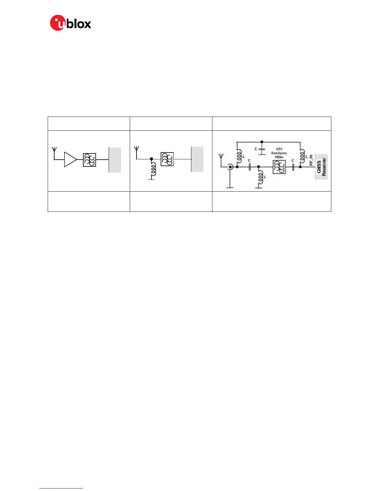
For robustness, EOS protection measures as shown in Figure 17 are recommended for designs
combining wireless communication transceivers (e.g. cellular) and GNSS in the same design or in
close proximity.
Small passive antennas (<2 dBic
and performance critical)
Passive antennas (>2 dBic or
performance sufficient)
Active antennas (without internal filter which
need the module antenna supervisor circuits)
LNA with appropriate ESD rating
and maximum input power
GNSS Band pass Filter: SAW or
Ceramic with low insertion loss
and appropriate ESD rating
Figure 17: EOS and ESD Precautions
Electromagnetic interference (EMI)
Electromagnetic interference (EMI) is the addition or coupling of energy, which causes a spontaneous
reset of the GNSS receiver or results in unstable performance. In addition to EMI degradation due to
self-jamming (see section 1.5), any electronic device near the GNSS receiver can emit noise that can
lead to EMI disturbances or damage.
The following elements are critical regarding EMI:
• Unshielded connectors (e.g. pin rows etc.)
• Weakly shielded lines on PCB (e.g. on top or bottom layer and especially at the border of a PCB)
• Weak GND concept (e.g. small and/or long ground line connections)
EMI protection measures are recommended when RF emitting devices are near the GNSS receiver. To
minimize the effect of EMI a robust grounding concept is essential. To achieve electromagnetic
robustness follow the standard EMI suppression techniques.
http://www.murata.com/products/emc/knowhow/index.html
http://www.murata.com/products/emc/knowhow/pdf/4to5e.pdf
Improved EMI protection can be achieved by inserting a resistor or better yet a ferrite bead or an
inductor (see Table 7) into any unshielded PCB lines connected to the GNSS receiver. Place the
resistor as close as possible to the GNSS receiver pin.
Alternatively, feed-thru capacitors with good GND connection can be used to protect e.g. the VCC
supply pin against EMI. A selection of feed-thru capacitors are listed in Table 7.
Intended use
☞ In order to mitigate any performance degradation of a radio equipment under EMC disturbance,
system integration shall adopt appropriate EMC design practice and not contain cables over three
meters on signal and supply ports.

 Loading...


