MAX-8 / MAX-M8 - Hardware Integration Manual
UBX-15030059 - R05 Product handling Page 24 of 31
Production Information
Unless there is a galvanic coupling between the local GND
(i.e. the work table) and the PCB GND, then the first point of
contact when handling the PCB must always be between
the local GND and PCB GND.
• Before mounting an antenna patch, connect ground of the
device
When handling the RF pin, do not come into contact with
any charged capacitors and be careful when contacting
materials that can develop charges (e.g. patch antenna ~10
pF, coax cable ~50 – 80 pF/m, soldering iron, …)
To prevent electrostatic discharge through the RF input, do
not touch any exposed antenna area. If there is any risk that
such exposed antenna area
is touched in non ESD
protected work area, implement proper ESD protection
When soldering RF connectors and patch antennas to the
receiver’s RF pin, make sure to use an ESD safe soldering
iron (tip).
⚠ Failure to observe these precautions can result in severe damage to the GNSS module!
ESD protection measures
⚠ GNSS positioning modules are sensitive to Electrostatic Discharge (ESD). Special precautions are
required when handling.
☞ For more robust designs, employ additional ESD protection measures. Using an LNA with
appropriate ESD rating can provide enhanced GNSS performance with passive antennas and
increases ESD protection.
Most defects caused by ESD can be prevented by following strict ESD protection rules for production
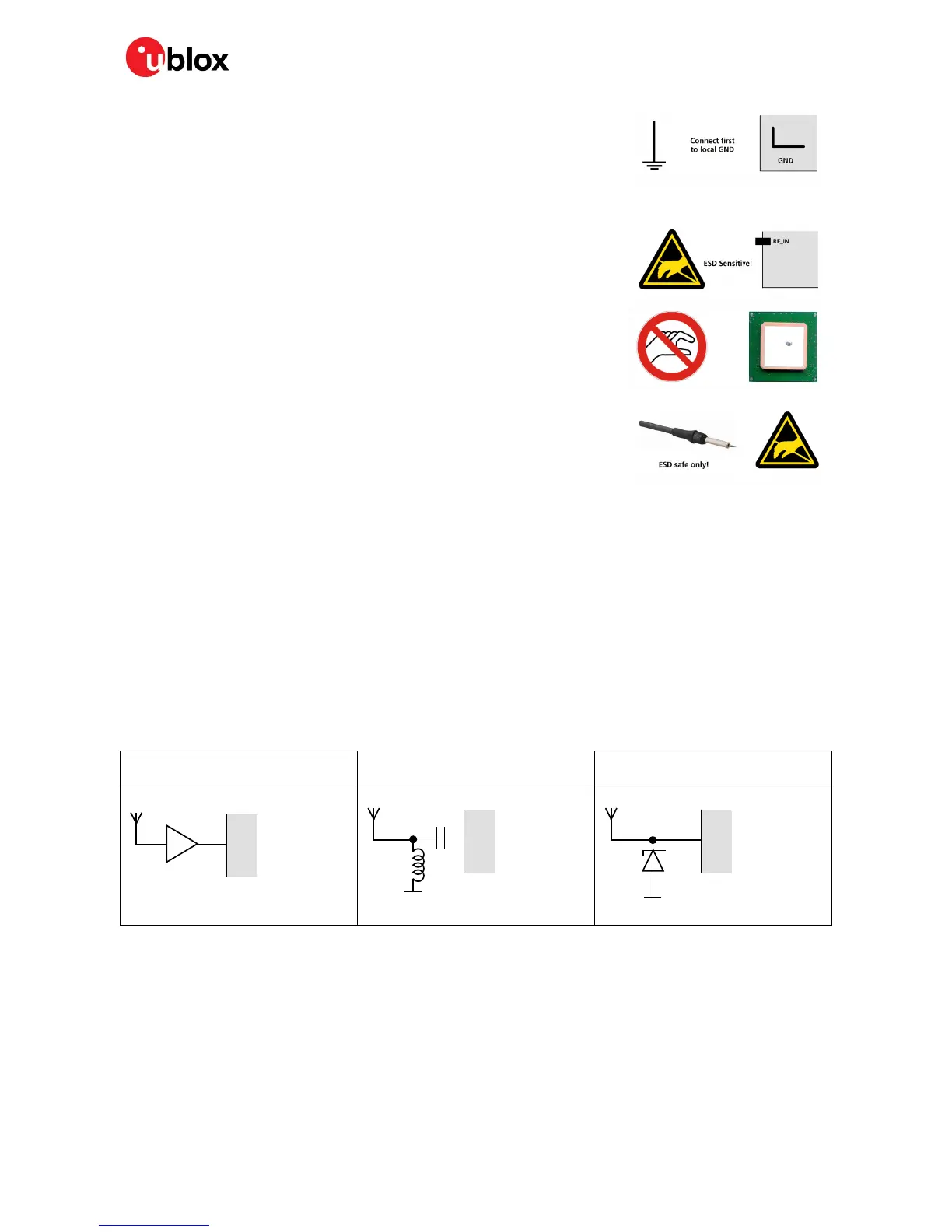
and handling. When implementing passive antenna patches or external antenna connection points,
then additional ESD measures can also avoid failures in the field as shown in Figure 16.
Small passive antennas (<2 dBic and
performance critical)
Passive antennas (>2 dBic or
performance sufficient)
Active antennas
LNA with appropriate ESD rating
Figure 16: ESD Precautions
☞ Protection measure A is preferred because it offers the best GNSS performance and best level of
ESD protection.
Electrical Overstress (EOS)
Electrical Overstress (EOS) usually describes situations when the maximum input power exceeds the
maximum specified ratings. EOS failure can happen if RF emitters are close to a GNSS receiver or its
antenna. EOS causes damage to the chip structures. If the RF_IN is damaged by EOS, it is hard to
determine whether the chip structures have been damaged by ESD or EOS.

 Loading...


