MAX-M10M-Integration manual
1.3 Pin assignment
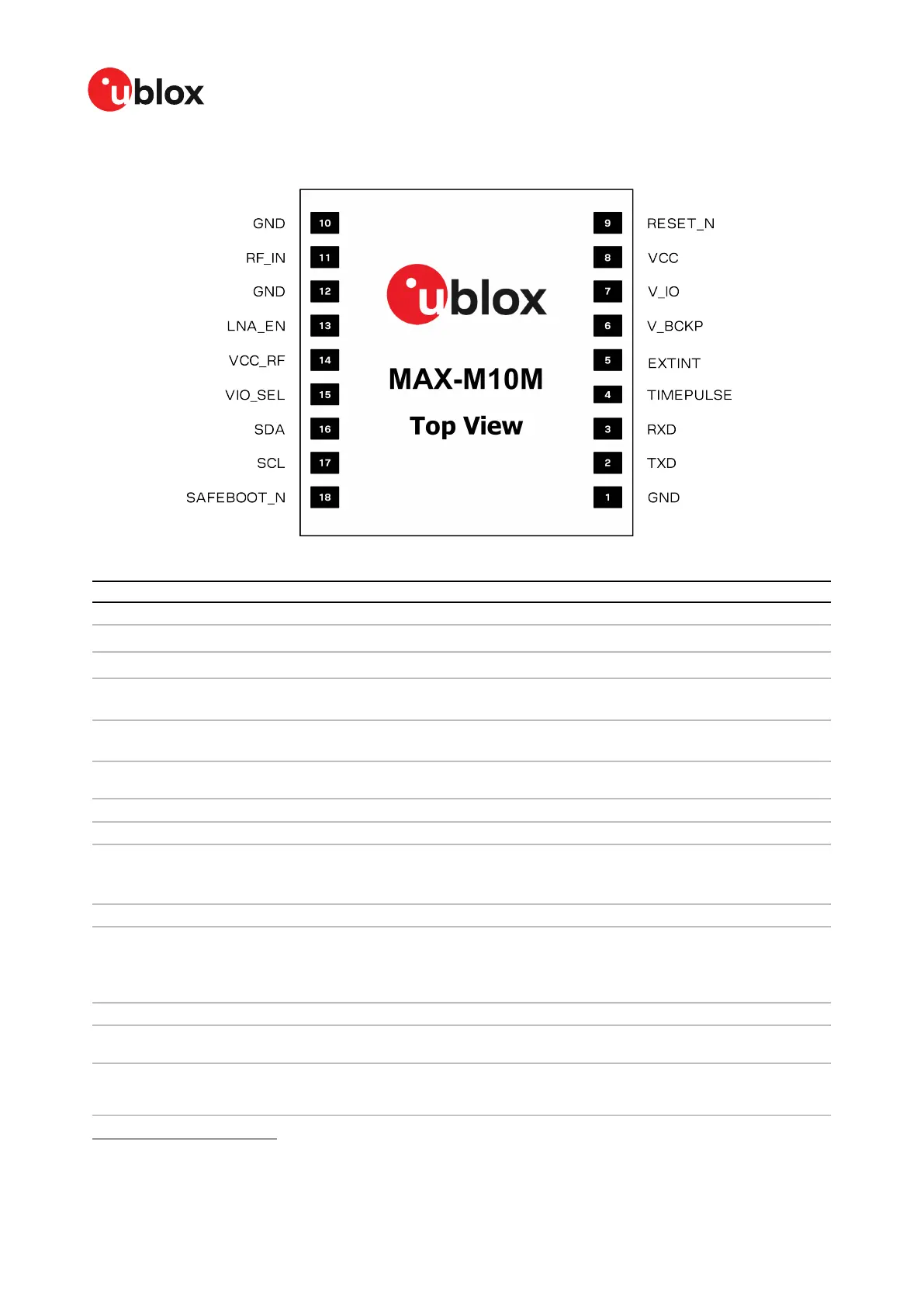
Figure 2: MAX-M10M pin assignment
Pin no. Name PIO no. I/O Description Remarks
1 GND - - - Connect to GND
2 TXD 1 O UART TX
If not used, leave open. Alternative functions
1
.
3 RXD 0 I UART RX
If not used, leave open. Alternative functions
1
.
4 TIMEPULSE 4 O Time pulse signal See section TIMEPULSE for more information.
Alternative functions
1
.
5 EXTINT 5 I External interrupt See EXTINT for more information. Alternative
functions
1
.
6 V_BCKP - I Backup voltage
supply.
Leave open if no external backup supply. See V_BCKP
for more information.
7 V_IO - I IO voltage supply See V_IO for more information.
8 VCC - I Main voltage supply See VCC for more information.
9 RESET_N - I System reset (active
low)
It has to be low for at least 1 ms to trigger a reset. Leave
open if not used.
See RESET_N section for more information.
10 GND - - - Connect to GND
11 RF_IN - I GNSS signal input
The RF signal line is DC blocked internally. The line
must match the 50 Ω impedance.
See sections RF front-end and Layout for more
information about the RF signal considerations.
12 GND - - - Connect to GND
13 LNA_EN - O On/Off external LNA
or active antenna
See LNA_EN for more information.
14 VCC_RF - O Output voltage RF
section
This pin supplies a filtered voltage that can be used
for optional external active antenna or LNA. This pin
is internally connected to VCC through a ferrite bead.
1
Alternatively, this pin can be used for ANT_DETECT, ANT_SHORT_N, TX_READY, and Data batching. Care must be taken
when the assigned function sets the pin as an output.
UBX-22038241 - R02
1 System description Page 7 of 92
C1-Public