SARA-G3 and SARA-U2 series - System Integration Manual
UBX-13000995 - R26 Design-in
Page 108 of 217
2.2.1.8 Guidelines for external battery charging circuit
Application devices that are powered by a Li-Ion (or Li-Polymer) battery pack should implement a suitable battery
charger design as SARA-G3 and SARA-U2 series modules do not have an on-board charging circuit.
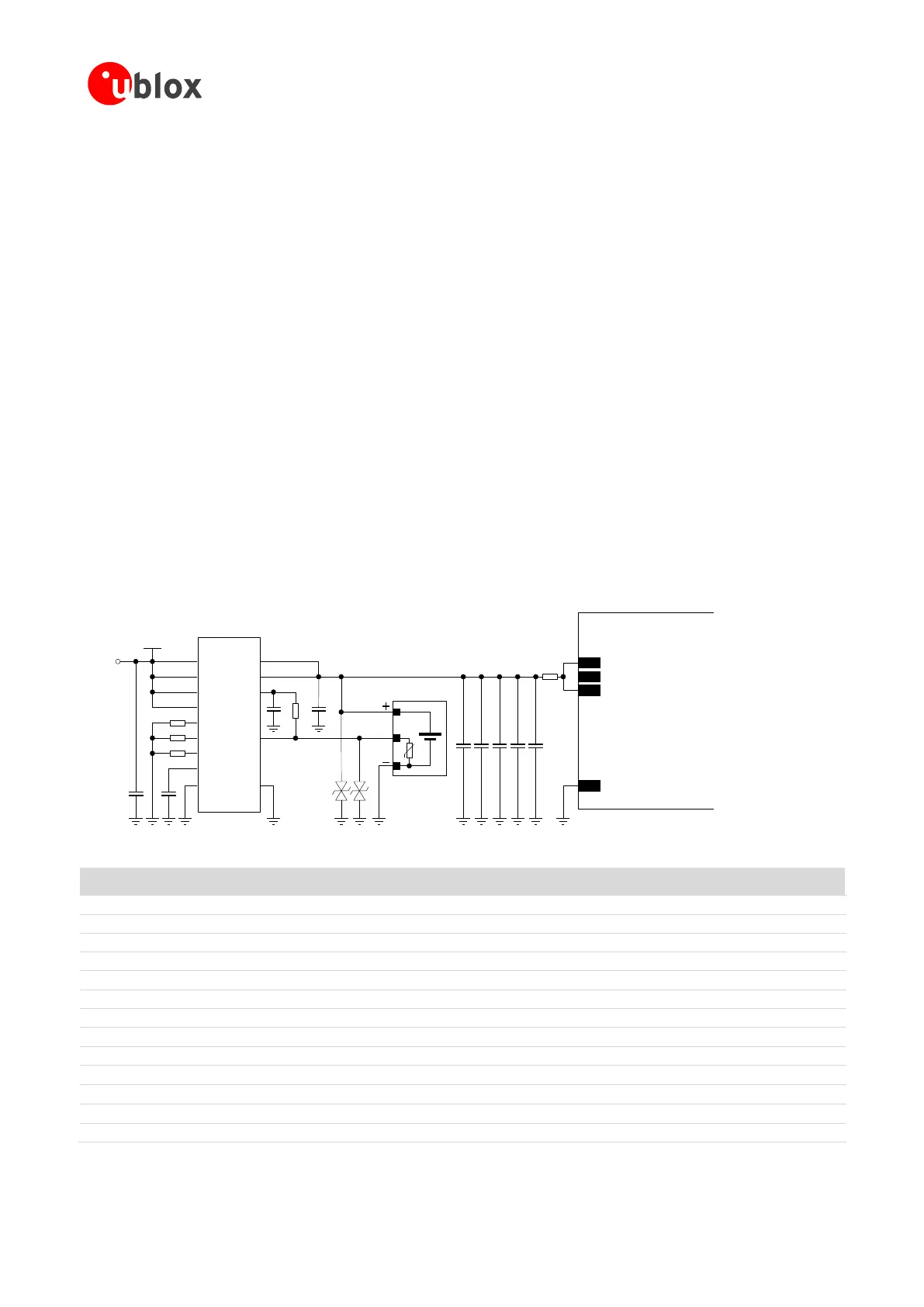
In the application circuit example described in Figure 48, a rechargeable Li-Ion (or Li-Polymer) battery pack, that
features proper pulse and DC discharge current capabilities and proper DC series resistance, is directly connected
to the VCC supply input of the module. Battery charging is fully managed by the STMicroelectronics L6924U
Battery Charger IC that, from a USB source (5.0 V typ.), charges as a linear charger the battery, in three phases:
Pre-charge constant current (active when the battery is deeply discharged): the battery is charged with a
low current, set to 10% of the fast-charge current
Fast-charge constant current: the battery is charged with the maximum current, configured by the value
of an external resistor to a value suitable for USB power source (~500 mA)
Constant voltage: when the battery voltage reaches the regulated output voltage (4.2 V), the L6924U
starts to reduce the current until the charge termination is done. The charging process ends when the
charging current reaches the value configured by an external resistor to ~15 mA or when the charging timer
reaches the value configured by an external capacitor to ~9800 s
Using a battery pack with an internal NTC resistor, the L6924U can monitor the battery temperature to protect
the battery from operating under unsafe thermal conditions.
The L6924U, as linear charger, is more suitable for applications where the charging source has a relatively low
nominal voltage (~5 V), so that a switching charger is suggested for applications where the charging source has
a relatively high nominal voltage (e.g. ~12 V, refer to the following section 2.2.1.9 for specific design-in), even if
the L6924U can also charge from an AC wall adapter as its input voltage range is tolerant up to 12 V: when a
current-limited adapter is used, it can operate in quasi-pulse mode, reducing power dissipation.
C5 C8
GND
C7C6 C9
SARA-G3 / SARA-U2
52
VCC
53
VCC
51
VCC
+
USB
Supply
C3
R4
θ
U1
IUSB
IAC
IEND
TPRG
SD
VIN
VINSNS
MODE
ISEL
C2C1
5V
TH
GND
VOUT
VOSNS
VREF
R1
R2
R3
Li-Ion/Li-Pol
Battery Pack
D1
B1
C4
Li-Ion/Li-Polymer
Battery Charger IC
D2
Ferrite Bead
or 0Ω
Figure 48: Li-Ion (or Li-Polymer) battery charging application circuit
Part Number - Manufacturer
Li-Ion (or Li-Polymer) battery pack with 470 NTC
1 µF Capacitor Ceramic X7R 0603 10% 16 V
GRM188R71C105KA12 - Murata
10 nF Capacitor Ceramic X7R 0402 10% 16 V
GRM155R71C103KA01 - Murata
1 nF Capacitor Ceramic X7R 0402 10% 50 V
GRM155R71H102KA01 - Murata
330 µF Capacitor Tantalum D_SIZE 6.3 V 45 m
T520D337M006ATE045 - KEMET
100 nF Capacitor Ceramic X7R 0402 10% 16 V
GRM155R61A104KA01 - Murata
56 pF Capacitor Ceramic C0G 0402 5% 25 V
GRM1555C1E560JA01 - Murata
15 pF Capacitor Ceramic C0G 0402 5% 25 V
GRM1555C1E150JA01 - Murata
Low Capacitance ESD Protection
24 k Resistor 0402 5% 0.1 W
RC0402JR-0724KL - Yageo Phycomp
3.3 k Resistor 0402 5% 0.1 W
RC0402JR-073K3L - Yageo Phycomp
1.0 k Resistor 0402 5% 0.1 W
RC0402JR-071K0L - Yageo Phycomp
Li-Ion (or Li-Polymer) Linear Battery Charger IC
L6924U - STMicroelectronics
Table 30: Suggested components for Li-Ion (or Li-Polymer) battery charging application circuit

 Loading...


