SARA-G3 and SARA-U2 series - System Integration Manual
UBX-13000995 - R26 Design-in
Page 109 of 217
2.2.1.9 Guidelines for external battery charging and power path management circuit
Application devices where both a permanent primary supply / charging source (e.g. ~12 V) and a rechargeable
back-up battery (e.g. 3.7 V Li-Pol) are available at the same time as possible supply source should implement a
suitable charger / regulator with integrated power path management function to supply the module and the
whole device while simultaneously and independently charging the battery.
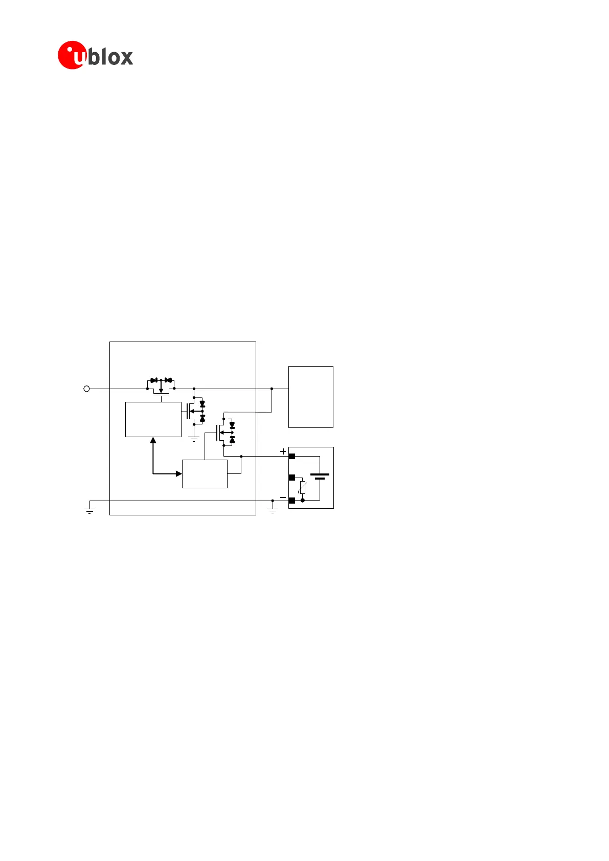
Figure 49 reports a simplified block diagram circuit showing the working principle of a charger / regulator with
integrated power path management function. This component allows the system to be powered by a permanent
primary supply source (e.g. ~12 V) using the integrated regulator which simultaneously and independently
recharges the battery (e.g. 3.7 V Li-Pol) that represents the back-up supply source of the system: the power path
management feature permits the battery to supplement the system current requirements when the primary
supply source is not available or cannot deliver the peak system currents.
A power management IC should meet the following prerequisites to comply with the module VCC requirements
summarized in Table 6:
High efficiency internal step down converter, compliant with the performances specified in section 2.2.1.2
Low internal resistance in the active path Vout – Vbat, typically lower than 50 m
High efficiency switch mode charger with separate power path control
GND
Power path management IC
VoutVin
θ
Li-Ion/Li-Pol
Battery Pack
GND
System
12 V
Primary
Source
Charge
controller
DC/DC converter
and battery FET
control logic
Vbat
Figure 49: Charger / regulator with integrated power path management circuit block diagram
Figure 50 and the components listed in Table 31 provide an application circuit example where the MPS MP2617
switching charger / regulator with integrated power path management function provides the supply to the
cellular module while concurrently and autonomously charging a suitable Li-Ion (or Li-Polymer) battery with
proper pulse and DC discharge current capabilities and proper DC series resistance according to the rechargeable
battery recommendations described in section 2.2.1.4.
The MP2617 IC constantly monitors the battery voltage and selects whether to use the external main primary
supply / charging source or the battery as supply source for the module, and starts a charging phase accordingly.
The MP2617 IC normally provides a supply voltage to the module regulated from the external main primary
source allowing immediate system operation even under missing or deeply discharged battery: the integrated
switching step-down regulator is capable to provide up to 3 A output current with low output ripple and fixed
1.6 MHz switching frequency in PWM mode operation. The module load is satisfied in priority, then the
integrated switching charger will take the remaining current to charge the battery.
Additionally, the power path control allows an internal connection from battery to the module with a low series
internal ON resistance (40 m typical), in order to supplement additional power to the module when the current
demand increases over the external main primary source or when this external source is removed.

 Loading...


