SARA-G3 and SARA-U2 series - System Integration Manual
UBX-13000995 - R26 System description
Page 48 of 217
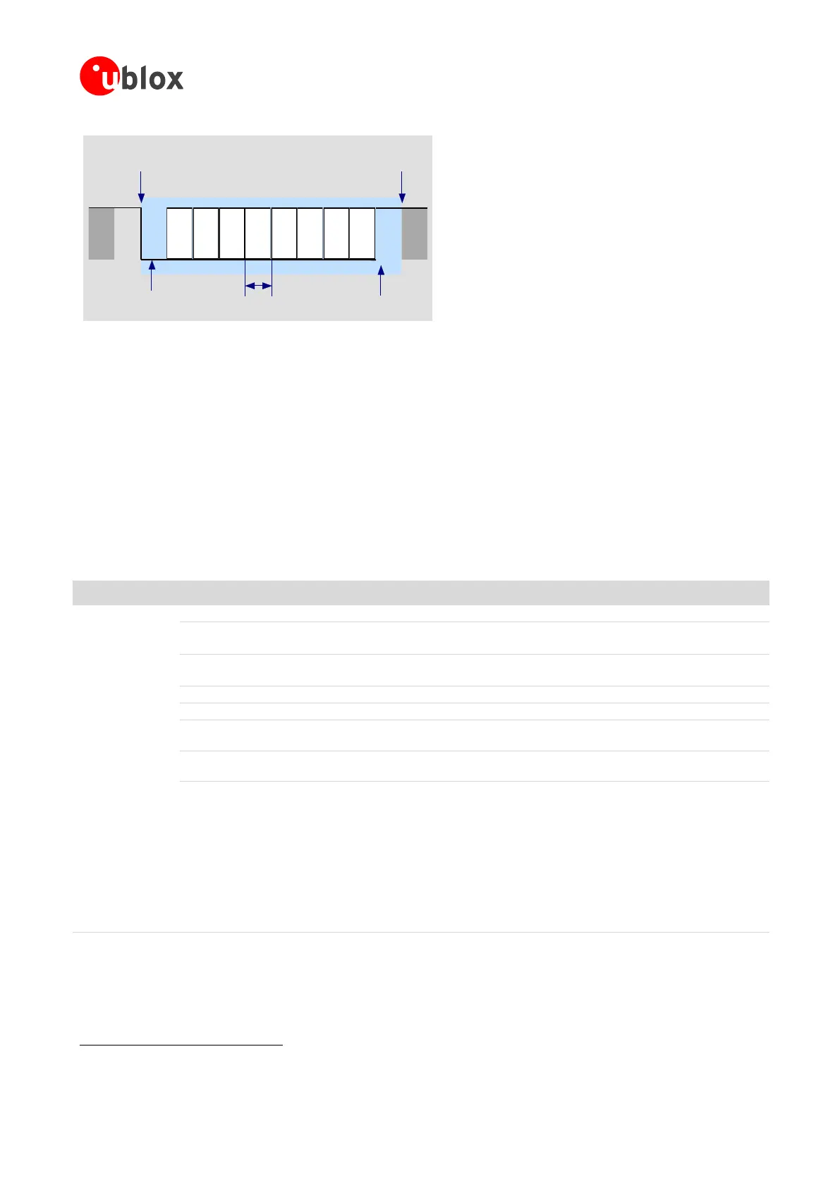
D0 D1 D2 D3 D4 D5 D6 D7
Start of 1-Byte
transfer
Start Bit
(Always 0)
Possible Start of
next transfer
Stop Bit
(Always 1)
t
bit
= 1/(Baudrate)
Normal Transfer, 8N1
Figure 25: Description of UART default frame format (8N1) with fixed baud rate
The module firmware can be updated over the UART interface by means of:
the Firmware upgrade Over AT (FOAT) feature, on all the SARA-G3 and SARA-U2 series modules
the u-blox EasyFlash tool, on SARA-U2 series modules only
For more details on FW upgrade procedures see section 1.13 and Firmware update application note [27].
1.9.1.2 UART AT interface configuration
The UART interface of SARA-G3 and SARA-U2 series modules is available as AT command interface with the
default configuration described in Table 10 (for more details and information about further settings, see the
u-blox AT Commands Manual [3]).
AT command mode is enabled by default on the UART physical interface
Automatic baud rate detection enabled by default on SARA-G3 series
One-shot automatic baud rate detection enabled by default on SARA-U2 series
Automatic frame format recognition enabled by default on SARA-G3 series
One-shot automatic frame format recognition enabled by default on SARA-U2 series
HW flow control enabled by default
DSR line set ON in data mode
30
and set OFF in command mode
30
Upon an ON-to-OFF transition of DTR, the DCE enters online command mode
30
and issues
an OK result code
Circuit 109 changes in accordance with the Carrier detect status; ON if the Carrier is
detected, OFF otherwise
Multiplexing mode is disabled by default and it can be enabled by AT+CMUX command.
The following virtual channels are defined:
Channel 0: control channel
Channel 1: AT and data
Channel 2: AT and data
Channel 3: AT and data (not available on SARA-G300 / SARA-G310 modules)
Channel 4: AT and data (not available on SARA-G300 / SARA-G310 modules)
Channel 5: AT and data (not available on SARA-G300 / SARA-G310 modules)
Channel 6: GNSS tunneling (not available on SARA-G300 / SARA-G310 modules)
Channel 7: SIM Access Profile (not available on SARA-G3 series modules)
Table 10: Default UART AT interface configuration
30
See the u-blox AT Commands Manual [3] for the definition of the command mode, data mode, and online command mode.

 Loading...


