SARA-G3 and SARA-U2 series - System Integration Manual
UBX-13000995 - R26 Design-in
Page 138 of 217
If RS-232 compatible signal levels are needed, the Maxim 13234E voltage level translator can be used. This chip
translates voltage levels from 1.8 V (module side) to the RS-232 standard.
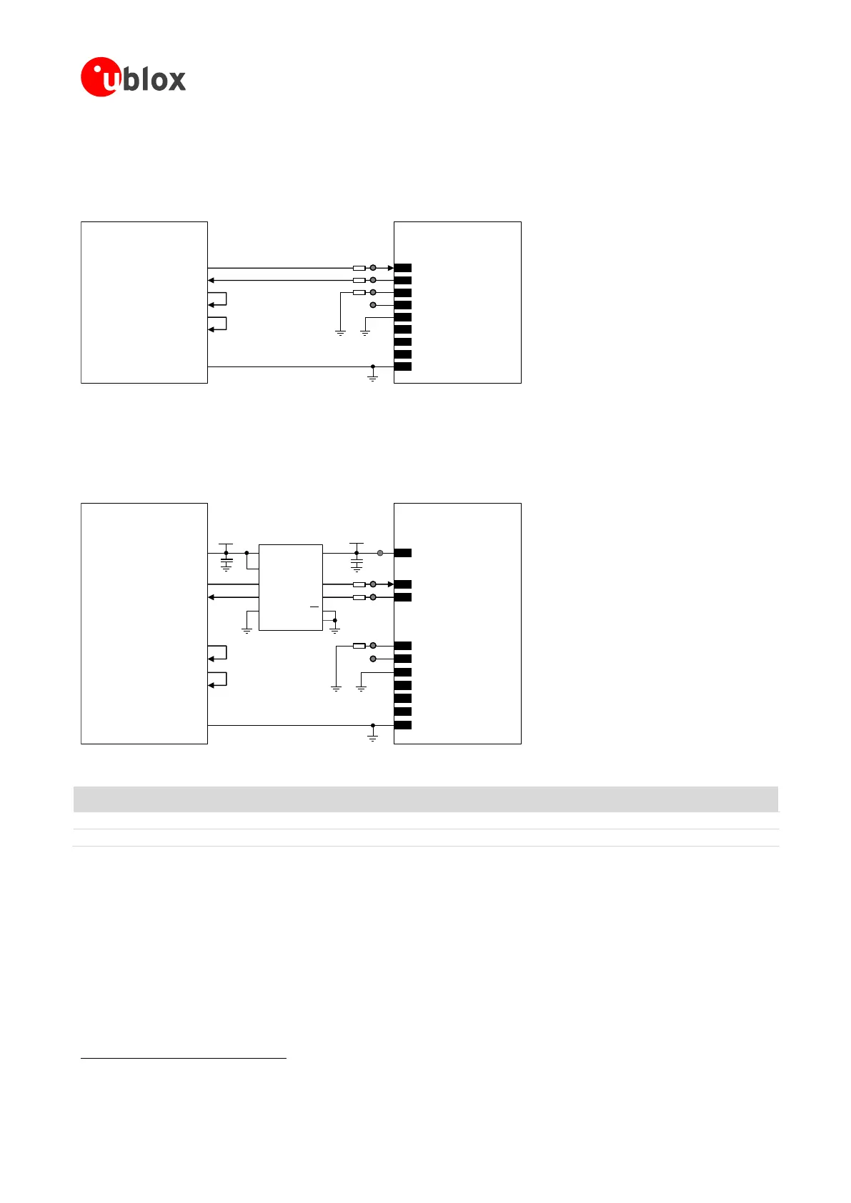
If a 1.8 V Application Processor (DTE) is used, the circuit that should be implemented as described in Figure 72:
TxD
Application Processor
(1.8V DTE)
RxD
RTS
CTS
DTR
DSR
RI
DCD
GND
SARA-G3 / SARA-U2
(1.8V DCE)
12
TXD
9
DTR
13
RXD
10
RTS
11
CTS
6
DSR
7
RI
8
DCD
GND
0Ω
TP
0Ω
TP
0Ω
TP
TP
Figure 72: UART interface application circuit with partial V.24 link (3-wire) in the DTE/DCE serial communication (1.8 V DTE)
If a 3.0 V Application Processor (DTE) is used, then it is recommended to connect the 1.8 V UART interface of the
module (DCE) by means of appropriate unidirectional voltage translators using the module V_INT output as
1.8 V supply for the voltage translators on the module side, as described in Figure 73.
4
V_INT
TxD
Application Processor
(3.0V DTE)
RxD
DTR
DSR
RI
DCD
GND
SARA-G3 / SARA-U2
(1.8V DCE)
12
TXD
9
DTR
13
RXD
6
DSR
7
RI
8
DCD
GND
1V8
B1 A1
GND
U1
VCCBVCCA
Unidirectional
Voltage Translator
C1
C2
3V0
DIR1
DIR2 OE
VCC
B2 A2
RTS
CTS
10
RTS
11
CTS
TP
0Ω
TP
0Ω
TP
0Ω
TP
TP
Figure 73: UART interface application circuit with partial V.24 link (3-wire) in DTE/DCE serial communication (3.0 V DTE)
Part Number - Manufacturer
100 nF Capacitor Ceramic X7R 0402 10% 16 V
GRM155R61A104KA01 - Murata
Unidirectional Voltage Translator
SN74AVC2T245
45
- Texas Instruments
Table 47: Component for UART application circuit with partial V.24 link (3-wire) in DTE/DCE serial communication (3.0 V DTE)
If only TXD and RXD lines are provided, as described in Figure 72 or in Figure 73, and HW flow-control is
disabled (AT&K0), the power saving must be enabled in this way:
AT+UPSV=1: the module automatically enters the low power idle mode whenever possible and the UART
interface is periodically enabled, as described in section 1.9.1.4, reaching low current consumption.
With this configuration, when the module is in idle mode, the UART is re-enabled 20 ms after the first data
reception, and the recognition of subsequent characters is guaranteed until the module is in active mode.
45
Voltage translator providing partial power down feature so that the DTE 3.0 V supply can be also ramped up before V_INT 1.8 V supply
 Loading...


