SARA-G3 and SARA-U2 series - System Integration Manual
UBX-13000995 - R26 Design-in
Page 142 of 217
2.6.3 Universal Serial Bus (USB)
USB interface is not supported by SARA-G3 modules.
2.6.3.1 Guidelines for USB circuit design
The USB_D+ and USB_D- lines carry the USB serial data and signaling. The lines are used in single-ended mode
for full speed signaling handshake, as well as in differential mode for high speed signaling and data transfer.
USB pull-up or pull-down resistors on USB_D+ and USB_D- as required by the Universal Serial Bus Revision 2.0
specification [14] are part of the USB pin driver and do not need to be externally provided.
Series resistors on USB_D+ and USB_D- as required by the Universal Serial Bus Revision 2.0 specification [14] are
also integrated and do not need to be externally provided.
Since the module acts as a USB device, the VBUS USB supply (5.0 V typ.) generated by the USB host must be
connected to the VUSB_DET input, which absorbs few microamperes to sense the host connection and enable
the USB interface of the module.
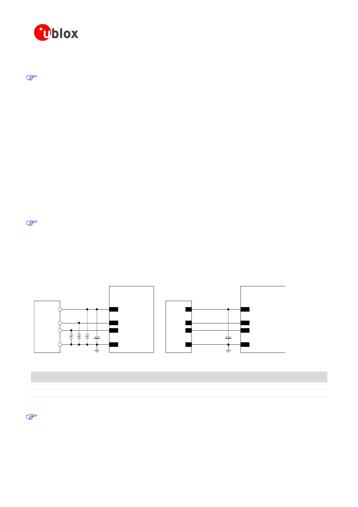
If connecting the USB_D+ and USB_D- pins to a USB device connector, the pin will be externally accessible on
the application device. According to the EMC/ESD requirements of the application, an additional ESD protection
device with very low capacitance should be provided close to accessible point on the line connected to this pin,
as described in Figure 76 and Table 49.
The USB interface pins ESD sensitivity rating is 1 kV (Human Body Model according to JESD22-A114F). A
higher protection level could be required if the lines are externally accessible and it can be achieved by
mounting a very low capacitance (i.e. less or equal to 1 pF) ESD protection (e.g. Tyco Electronics
PESD0402-140 ESD protection device) on the lines connected to these pins, close to accessible points.
The USB pins of the modules can be directly connected to the USB host application processor without additional
ESD protections if they are not externally accessible or according to EMC/ESD requirements.
SARA-U2 series
D+
D-
GND
29
USB_D+
28
USB_D-
GND
USB DEVICE
CONNECTOR
D1 D2
VBUS
SARA-U2 series
D+
D-
GND
29
USB_D+
28
USB_D-
GND
USB HOST
PROCESSOR
C1
17
VUSB_DET
C1
17
VUSB_DET
VBUS
D3
Figure 76: USB Interface application circuits
Part Number - Manufacturer
100 nF Capacitor Ceramic X7R 0402 10% 16 V
GRM155R61A104KA01 - Murata
Very Low Capacitance ESD Protection
PESD0402-140 - Tyco Electronics
Table 49: Component for USB application circuits
If the USB interface is not required by the customer application, as the UART interface is used for AT and
data communication with the host application processor, the USB pins can be left unconnected, but it is
highly recommended to provide direct access on the application board by means of accessible test-point
directly connected to the VUSB_DET, USB_D+, USB_D- pins of SARA-U2 modules.
 Loading...


