SARA-G3 and SARA-U2 series - System Integration Manual
UBX-13000995 - R26 Design-in
Page 160 of 217
switch (e.g. Texas Instruments SN74CB3Q16244, TS5A3159, or TS5A63157) between the two-circuit
connections and set to high impedance during module power down mode and power-on sequence.
It is highly recommended to provide direct access to the GPIO3 pin of SARA-G3 modules product versions
“02” onwards for diagnostic purposes: provide a test-point on each line to accommodate the access and
provide a 0 series resistor on each line to detach the module pin from any other connected device.
If the GPIO pins are not used, they can be left unconnected on the application board, but a test-point
connected to GPIO3 pin of SARA-G3 modules product versions “02” onwards is highly recommended.
2.8.1.2 Guidelines for GPIO layout design
The general purpose input/output pins are generally not critical for layout.
2.9 Reserved pins (RSVD)
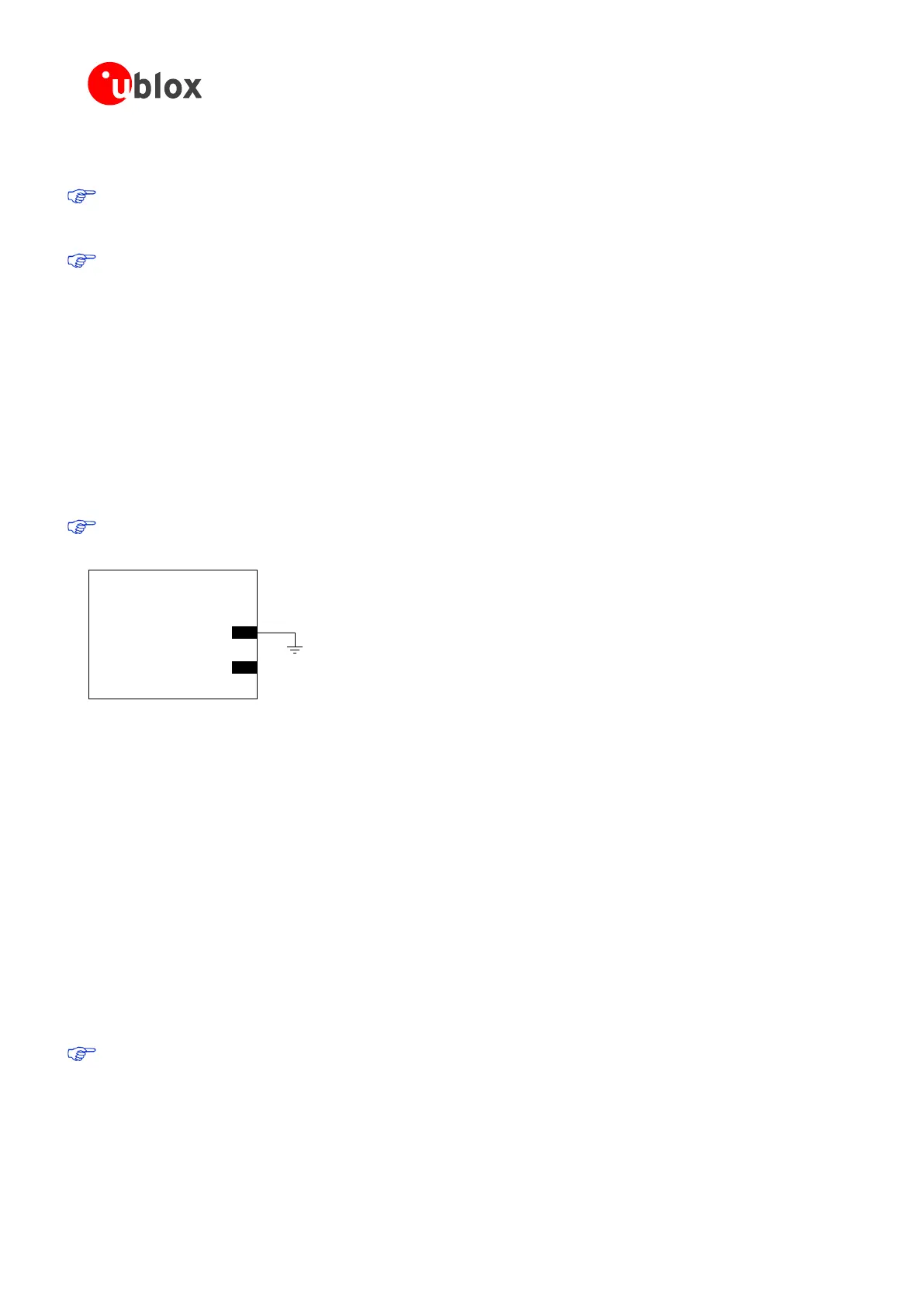
SARA-G3 and SARA-U2 series modules have pins reserved for future use. All the RSVD pins, except pin number
33, can be left unconnected on the application board. Figure 89 illustrates the application circuit.
Pin 33 (RSVD) must be connected to GND.
SARA-G3 / SARA-U2
33
RSVD
RSVD
Figure 89: Application circuit for the reserved pins (RSVD)
2.10 Module placement
Optimize placement for minimum length of RF line and closer path from DC source for VCC.
Make sure that the module, RF and analog parts / circuits are clearly separated from any possible source of
radiated energy, including digital circuits that can radiate some digital frequency harmonics, which can produce
Electro-Magnetic Interference affecting module, RF and analog parts / circuits’ performance or implement proper
countermeasures to avoid any possible Electro-Magnetic Compatibility issue.
Make sure that the module, RF and analog parts / circuits, high speed digital circuits are clearly separated from
any sensitive part / circuit which may be affected by Electro-Magnetic Interference or employ countermeasures to
avoid any possible Electro-Magnetic Compatibility issue.
Provide enough clearance between the module and any external part: clearance of at least 0.4 mm per side is
recommended to let suitable mounting of the parts.
The heat dissipation during transmission at maximum power can raise the temperature of the module and
its environment, as the application board locations near and below the SARA-G3 series modules and,
more significantly, the locations near and below the SARA-U2 series modules: avoid placing temperature
sensitive devices close to the module.
 Loading...


