SARA-G3 and SARA-U2 series - System Integration Manual
UBX-13000995 - R26 Design-in
Page 140 of 217
2.6.2 Auxiliary asynchronous serial interface (UART AUX)
Auxiliary UART interface is not supported by SARA-U2 "00", "03", "53", "63", "73" product versions.
2.6.2.1 Guidelines for UART AUX circuit design
The auxiliary UART interface can be connected to an application processor for AT command mode and/or GNSS
tunneling mode (the latter is supported by SARA-G3 modules product versions “02” onwards).
Pass-through mode capability of the application processor might be considered to provide access to the auxiliary
UART interface for SARA-G3 modules’ firmware upgrade by means of the u-blox EasyFlash tool and for
diagnostic purposes.
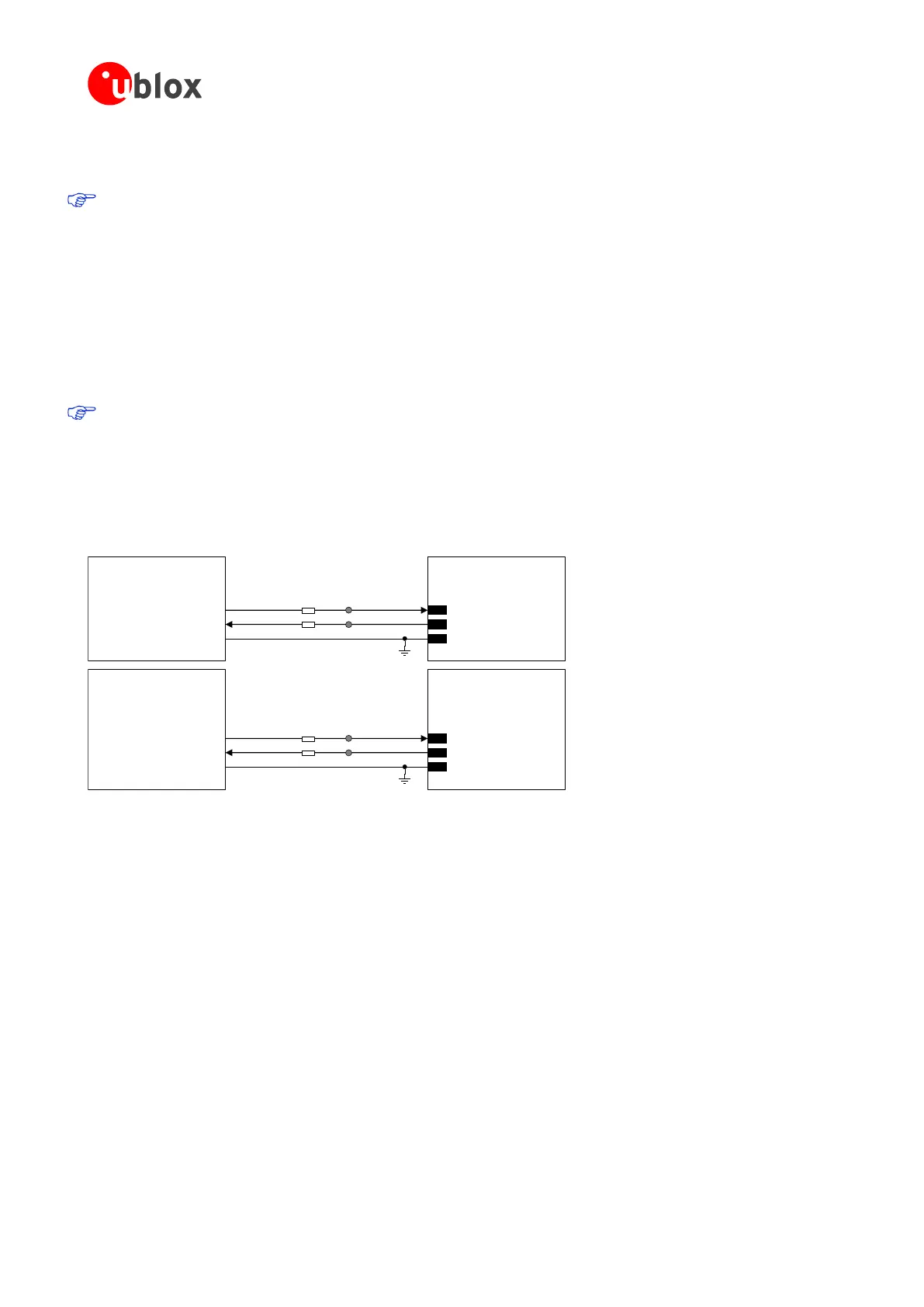
It is highly recommended to provide direct access to the TXD_AUX, RXD_AUX pins of SARA-G3 modules
for execution of firmware upgrade over auxiliary UART using the u-blox EasyFlash tool and for diagnostic
purposes: provide a test-point on each line to accommodate the access and provide a 0 series resistor
on each line to detach the module pin from any other connected device.
The circuit with a 1.8 V application processor should be implemented as described in Figure 74.
TxD
Application Processor
(1.8V DTE)
RxD
SARA-G3 series
(1.8V DCE)
29
TXD_AUX
28
RXD_AUX
GND GND
0 ohm
0 ohm
TestPoint
TestPoint
TxD
Application Processor
(1.8V DTE)
RxD
SARA-U2 series
(versions ‘04’ onwards)
(1.8V DCE)
26
SDA
27
SCL
GND GND
0 ohm
0 ohm
TestPoint
TestPoint
Figure 74: UART AUX interface application circuit connecting a 1.8 V application processor
 Loading...


