SARA-G3 and SARA-U2 series - System Integration Manual
UBX-13000995 - R26 System description
Page 35 of 217
1.6 System function interfaces
1.6.1 Module power-on
1.6.1.1 Switch-on events
Table 8 summarizes the possible switch-on events for the SARA-G3 and SARA-U2 series modules.
Applying valid VCC supply voltage (i.e. VCC rise edge),
ramping from 2.5 V to 3.2 V within 4 ms
Applying valid VCC supply voltage (i.e. VCC rise edge),
ramping from 2.5 V to 3.2 V within 1 ms
Low level on PWR_ON pin for 5 ms min
Low pulse on PWR_ON pin for 50 µs min / 80 µs max
RTC alarm programmed by AT+CALA command
(Not supported by SARA-G300 / SARA-G310)
RTC alarm programmed by AT+CALA command
RESET_N pin released from low level
Table 8: Summary of SARA-G3 and SARA-U2 modules’ switch-on events
When the SARA-G3 and SARA-U2 series modules are in the not-powered mode (i.e. switched off with the VCC
module supply not applied), they can be switched on by:
Rising edge on the VCC supply input to a valid voltage for modules supply: the modules switch on applying
VCC supply starting from a voltage value lower than 2.25 V, providing a fast VCC voltage slope, as it must
ramp from 2.5 V to 3.2 V within 4 ms on SARA-G3 modules and within 1 ms on SARA-U2 modules, and
reaching a proper nominal VCC voltage value within the normal operating range.
Alternatively, the RESET_N pin can be held low during the VCC rising edge, so that the module switches on
by releasing the RESET_N pin when the VCC voltage stabilizes at its nominal value within the normal range.
The status of the PWR_ON input pin of SARA-G3 and SARA-U2 series modules while applying the VCC module
supply is not relevant: during this phase, the PWR_ON pin can be set high or low by the external circuit.
When the SARA-G3 and SARA-U2 series modules are in the power-off mode (i.e. switched off by means of the
AT+CPWROFF command, with valid VCC module supply applied), they can be switched on by:
Low level / pulse on PWR_ON pin, which is normally set high by an external pull-up, for a valid time period.
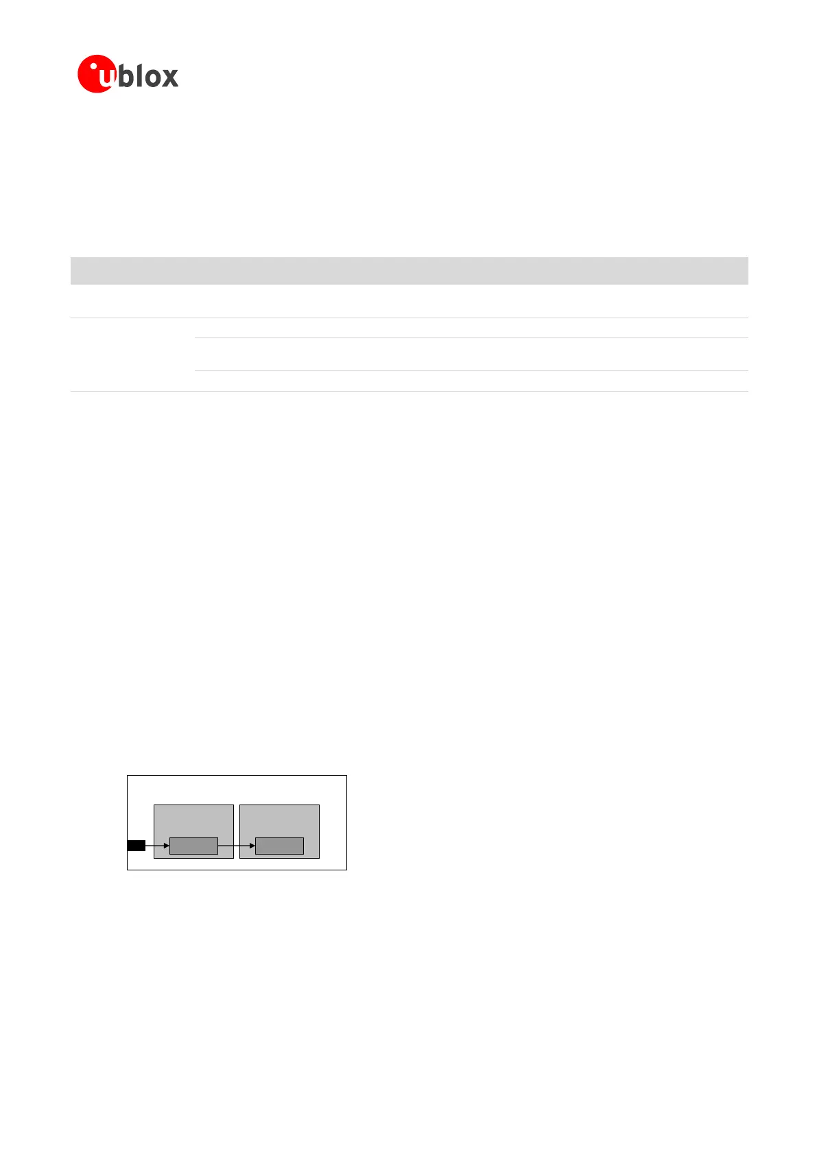
As described in Figure 20, there is no internal pull-up resistor on the PWR_ON pin of the modules: the pin has
high input impedance and is weakly pulled high by the internal circuit. Therefore the external circuit must be
able to hold the high logic level stable, e.g. providing an external pull-up resistor (for design-in see section 2.3.1).
The PWR_ON input voltage thresholds are different from the other generic digital interfaces of the modules: see
the SARA-G3 series Data Sheet [1] and the SARA-U2 series Data Sheet [2] for detailed electrical characteristics.
Baseband
Processor
15
PWR_ON
SARA-G3 / SARA-U2 series
Power-on
Power
Management
Power-on
Figure 20: PWR_ON input description
The SARA-G340, SARA-G350 and SARA-U2 series can be also switched on from power-off mode by:
RTC alarm pre-programmed by the AT+CALA command at a specific time (see the u-blox AT Commands
Manual [3]).
The SARA-U2 series modules can be also switched on from power-off mode by:
Low pulse on the RESET_N pin, which is normally set high by an internal pull-up (see section 1.6.3 and the
SARA-U2 series Data Sheet [2] for the description of the RESET_N input electrical characteristics).
 Loading...


