SARA-R5 series - System integration manual
UBX-19041356 - R04 Design-in Page 68 of 118
C1-Public
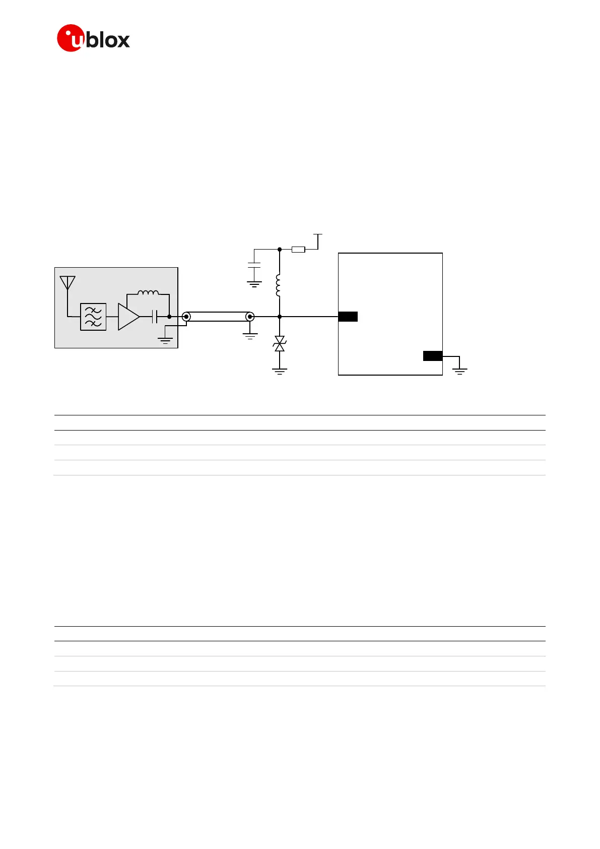
To avoid damaging the bias-T series inductor in the case of a short circuit at the antenna connector,
it is recommended to implement a proper over-current protection circuit, which may consist in a series
resistor as in the example illustrated in Figure 44. Component values are calculated according to the
characteristics of the active antenna and the related supply circuit in use: the value of R
bias
is
calculated such that the maximum current capacity of the inductor L is never exceeded. Moreover
R
bias
and C form a low pass filter to remove high frequency noise from the DC supply. Assuming
VCC_ANT=3.3 V, Table 26 reports suggested components for the circuit in Figure 44.
The recommended bias-t inductor (Murata LQW15ANR12J00) has a maximum current capacity of
110 mA. Hence the current is limited to 100 mA by way of a 33 ohm bias resistor. This resistor power
rating must be chosen to ensure reliability in the chosen circuit design.
SARA-R51 0M8S
31
ANT_GNSS
GND
LNA
Active antenna
Coaxial antenna
cable
VCC_ANT
Rbias
C
L
ESD
Figure 44: Typical circuit with active antenna connected to GNSS RF interface of SARA-R510M8S, using an external supply
Part number - Manufacturer
120 nH wire-wound RF Inductor 0402 5% 110 mA
100 nF capacitor ceramic X7R 0402 10% 16 V
GCM155R71C104KA55 - Murata
Table 26: Example component values for active antenna biasing
☞ Refer to the antenna data sheet and/or manufacturer for proper values of the supply voltage
VCC_ANT, inductance L and capacitance C.
☞ ESD sensitivity rating of the ANT_GNSS RF input pin is 1 kV (HBM according to JESD22-A114).
Higher protection level can be required if the line is externally accessible on the application board.
Higher protection level can be achieved by mounting an ultra-low capacitance (i.e. less than 1 pF)
ESD protection (see Table 27) close to accessible point.
Table 27 lists examples of ESD protection suitable for the GNSS RF input of SARA-R510M8S.
ESD protection diode with ultra−low capacitance (0.5 pF)
ESD protection diode with ultra−low capacitance (0.4 pF)
ESD protection diode with ultra−low capacitance (0.25 pF)
Table 27: Examples of ultra−low capacitance ESD protections

 Loading...


