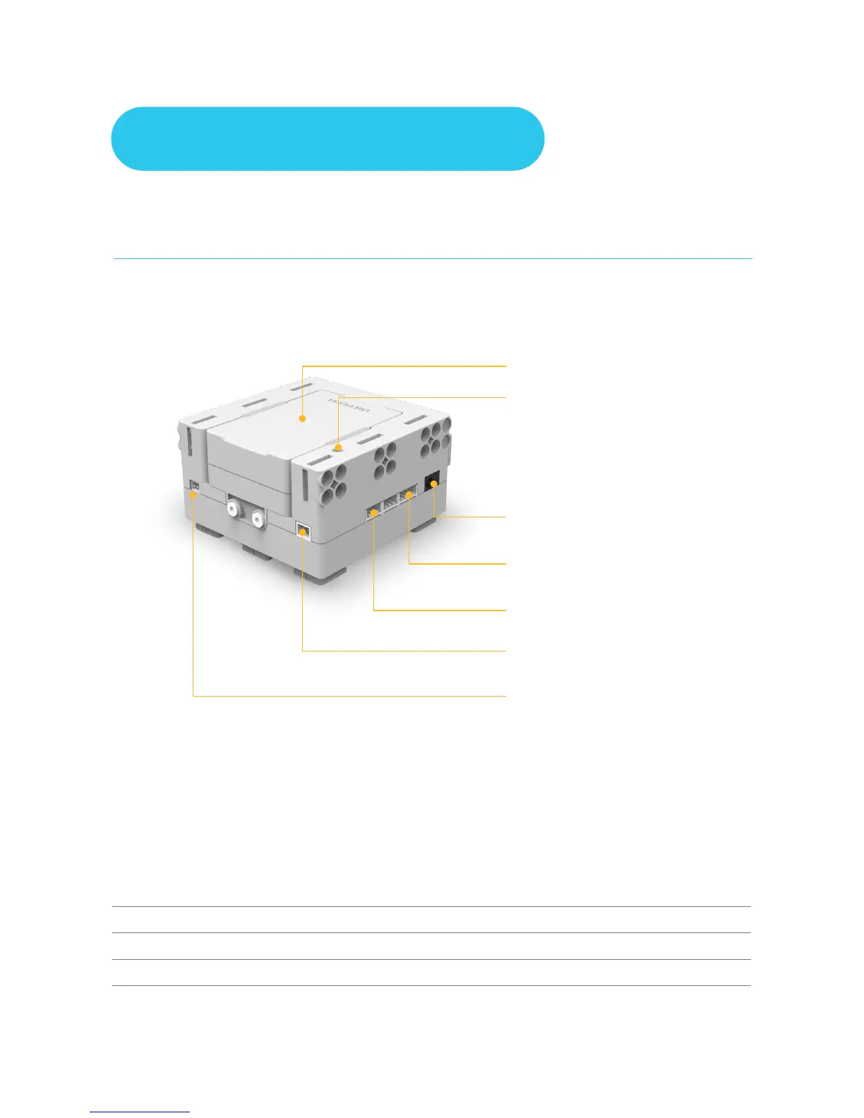
The brain of a Jimu robot is a Main control box. Once the mobile phone has connected over
wireless to the main control box, it can be used to control the Jimu robot. There is an exclusive
MAC address for the controller on its back. The Main control box has slots, plugs and ports,
which allows the robot be assembled by splicing, integrating, and connecting.
Note:
For more information about ports , please refer to:
Assembly Introduction - Connections
Motherboard Specifications
Processor - STM32F070
Memory - 4M
Communication - dual-mode Bluetooth 3.0/4.0 BLE+EDR
1.Main Control Box
Battery
Power Indicator
Located on the left side of the main control box, it
indicates the current power status of the main control
box. Statuses as displayed by the indicator are as follows:
Red = charging
Green = fully charged
Flashing green = operating
Charging Interface
Used to charge the controller
4-Pin Cable Connector
For connecting the 4-pin sensors
3-Pin Cable Connector
For connecting the 3-pin servos or sensors
External LED Interface
For connecting external LED
Power Switching Interface
For connecting the power switch
Components Introduction
1