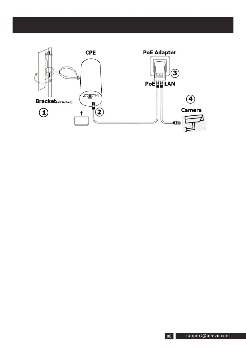
1. Place the CPE to the selected position and adjust the CPE front panel orientation
to be approximately the same as the selected direction, then use the ties to fix the
CPE, the bracket is not included in the package. Recommended UeeVii Universal
Bracket (ASIN: B09NLLG8MZ).
2. Please, prepare a long enough network cable to connect the PoE adapter and CPE,
the network cable is connected to the LAN port of the CPE, and the other end is
connected to the PoE port of the PoE adapter. Recommend to use a cat 5 (or above)
shielded network cable with a ground wire.
3. Connect the PoE adapter PoE to CPE, and LAN to Camera, PC, Router or Switch
based on the network topology. The role of PoE is to provide power and data
transmission for CPE.
4. The master CPE’s PoE adapter’s LAN connection monitors the Internet, and the
slave CPE’s PoE adapter LAN connects cameras or routers and other equipment.
Installation Tips:
1. For installation, the line of sight of the 2 wireless bridge brackets must be clear and
cannot pass through the wall. There is no strong electricity, strong magnetism, and
other signal interference between the two wireless bridges.
2. The signal transmission angle of the wireless bridge is 60°, for point-to-multipoint
installation, the angle of the slave bridge needs to be adjusted to ensure that it is
within the 60-degree signal range of the main bridge. The antenna polarization
direction is horizontal 60°/vertical 30°.
Installation
 Loading...