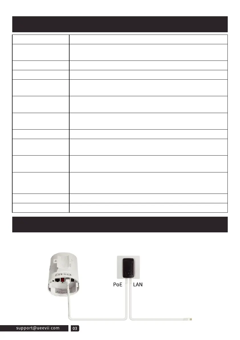
The wireless bridge adopts a PoE power supply, which is easy to install and
manage while saving costs.
Detailed Description
PoE Power Supply
Digital Tube
Digital Tube
Digital Tube
Point LED
A-B Button
RST Button
RST Button
PWR
LAN1/LAN2
WLAN Signal LED
Item
PoE Port
LAN Port
Description
A, B status lights, lighting is B mode, no lighting is A mode.
WLAN is solid red light indicates successful pairing,
4 grid green signal strength display
When LAN1 and LAN2 are connected is solid.
Power indicator, red LED solid is normal
Digital tube display "L" and flashing indicates in settings
status
Digital tube flashing indicates setting the config or connecting,
solid light indicates that the pairing has been successful.
Digital tube display "H" indicates in manual configuration
status
Click once to switch between different characters, looping from
0, 1, ..., F. Characters represent channels.cessful.
Long-press 10s on the "RST” button and the bridge will
auto-reset.
24V power supply and data transmission.
Only data transfer, 100Mbps RJ45 port
The bridge switches the master and slave bridges through the
A-B button, A represents the master bridge, and B represents
the slave bridge.
 Loading...