impedance and a 6.3-mm phono plug (Iike
that
01
UHER W
766
or W 776).
2.2 MONITOR
Output
(2)
This socket is for connecting the recorder (via
UHER
stereo
lead K 541) to
an
amplifier or preamplifier/control centre that
is equipped with a monitor input.
2.3
Accessory
Input
"ZUSATZGERÄTE"
'"
(3)
Connect
UHER
PSU
and battery recharger Z 124
Al,
UHER
remote-control
startlstop
switches F
111
and F
211
cr
UHER
"Akustomat"
F413
to
this socket.
2.4 RADIO PHONO
Inpul!
Output
(4)
This socket is a combined input and
output
for
connection
to
a stereo tuner, receiver
cr
amplifier that is equipped with DIN
socketry. Use
UHER
inter-unit lead K
511
(mono) or K
541
(stereo)
to
connect
the
recorder to the
TAPE
socket
01
the
radio or amplifier.
Ta avoid lass
of
high frequencies
in
record
and
playback, con-
necling leads K
511
or K
541
should be extended only by
experienced service technicians, and
thsn
only
if
the
output
(mpedance
of
the
input soures permits. Record-players with
crystal pick-ups
mayaiso
be connected
to
the high-level input
01
th·,s
socket
(p·,ns
3/5
in parallel and 2 - 2
~
ground)
2.5 Microphone
Input
(5)
This socket is for connecting low-impedance microphones Iike
UHER
M 518, with the remote-control switching
of
which tape
transport may be interrupted (remote stop: pins 6 and 7) by
simply holding down
the
switch on
the
microphone.
Pin 8 is charged
with"
+"voltage for powering a low-impedance_
electret condenser microphone (Iike
UHER
M 646) directly
from
the
recorder.
2,6
AV
Input/Output
(6)
This socket is for connecting accessory equipment used
in
the double-track interlock method
of
synchronizing sound and
lilm
(DIN
15970).
When recording sound by this method. sync
of
sound and
picture may be achieved by controlling either the speed
of
the
film projector
(caUed
as
in
professional film recording
"forward
contrai")
or
that
of
the open-reel tape recorder
("backward
control").
With
the
proper accessary, 1000-Hz pulses delivered by a film
camera - at, for example, every picture or every fourth picture
- (according to the system used) may serve
as
the
basis for
regulating the speed.
In
filming with live sound, the 1000-Hz pulses generated by
the
film camera are stored
together
with
the
sound recording
on separate tracks
of
the
tape (track 1 - sound track, track 3 -
pulse track).
To
this end, the pulse track system leads of the special AV
record/playback head are run out to contacts 6 and 3 (3
ground)
of
the
AV
socket.
For
the
backward
control
required with a number
of
sync
systems
in
playback
of
sound and film, it is necessary
to
alter
the
regulation
of
the motor electronics by running
an
ATe lead
to
contact 2
of
the AV socket.
When seI
10
the
START
lunction,
the
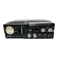
4000
REPORT
MONITOR
will be switched to REMOTE
STOP
once conlacts 5 and 4
(4
= ground)
ofthe
AV
socket are connected together. During
Ihis
time the yellow
LED
indicator (27) will light up.
Forward
control
is needed
in
the
unified sound system, for
example, while
backward
control
must be employed
in
sys-
tems like the Gigge Syn 2000, Synputer prolessional, Unisync
and Synchromaster.
25


 To Next Page