VLS Service Manual - REV2015.04
Table of Contents
Adjustments and Settings
Page | 12
Adjustments and Settings
CPU Initialization / Auto-Z Calibration
NOTE: This procedure must be performed with the aluminum Engraving Table installed. Do not use the
honeycomb Cutting Table for this procedure. Make sure that there are no accessories, materials, or pieces of
material on the table when doing the calibration.
Power up both the computer and the VLS. Home the Z-Axis by clicking the HOME Z button on the VIEWER tab
of the UCP.
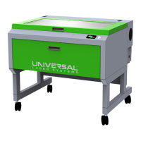
1. Using the UP and DOWN arrow buttons, either on the machine (on the front keypad) or in the UCP,
bring the Z-axis table up.
2. Using the appropriate Focus Tool for the lens installed, focus directly on the surface of the table.
Out of Focus: The table is to low. Correct Focal Height
NOTE: If you are unable to focus to the surface of the Engraving Table due to the system preventing you from
raising the table. You may be able to address this in the calibrate window. Use the UP or DOWN arrows to move
the table as needed.
3. In the UCP, click the System tab and choose the appropriate lens size from the Lens Size list.
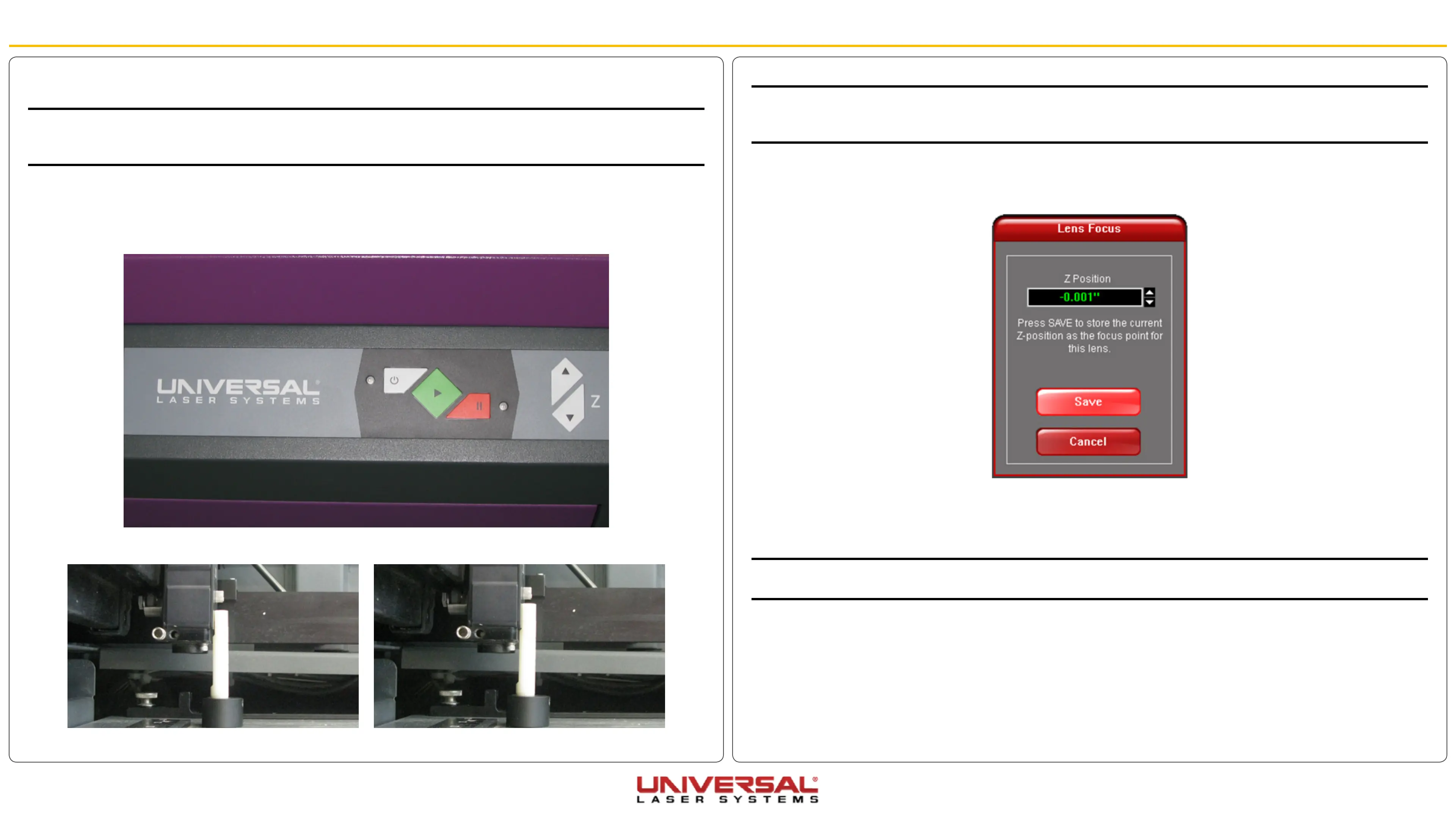
4. On the System tab, under Lens Size, click Calibrate. The following window appears:
5. Click Save to accept the new Z Position, then click Yes when asked if you are sure you want to override
the value.
6. The Lens is now calibrated.
NOTE: if you have purchased additional lens kits, calibrate the lens kit according to steps 1 through 4. Be sure
to select the proper lens size from the list before calibrating.
7. Calibration of the Lens Size and the Auto Z feature is now complete on the standard engraving table.