VLS Service Manual - REV2015.04
Table of Contents
Component Removal and Replacement
Page | 43
Component Removal and Replacement
4. Lift the system straight up and carefully tilt to set it on its side on a dolly or furniture cart. Relocate as
necessary.
5. Assembly is opposite of disassembly.
VLS6.60
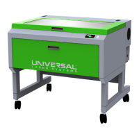
1. Secure the X-axis Arm inside the system. This is normally done by wrapping a rubber band around the
arm and securing it to the Y-axis Motor.
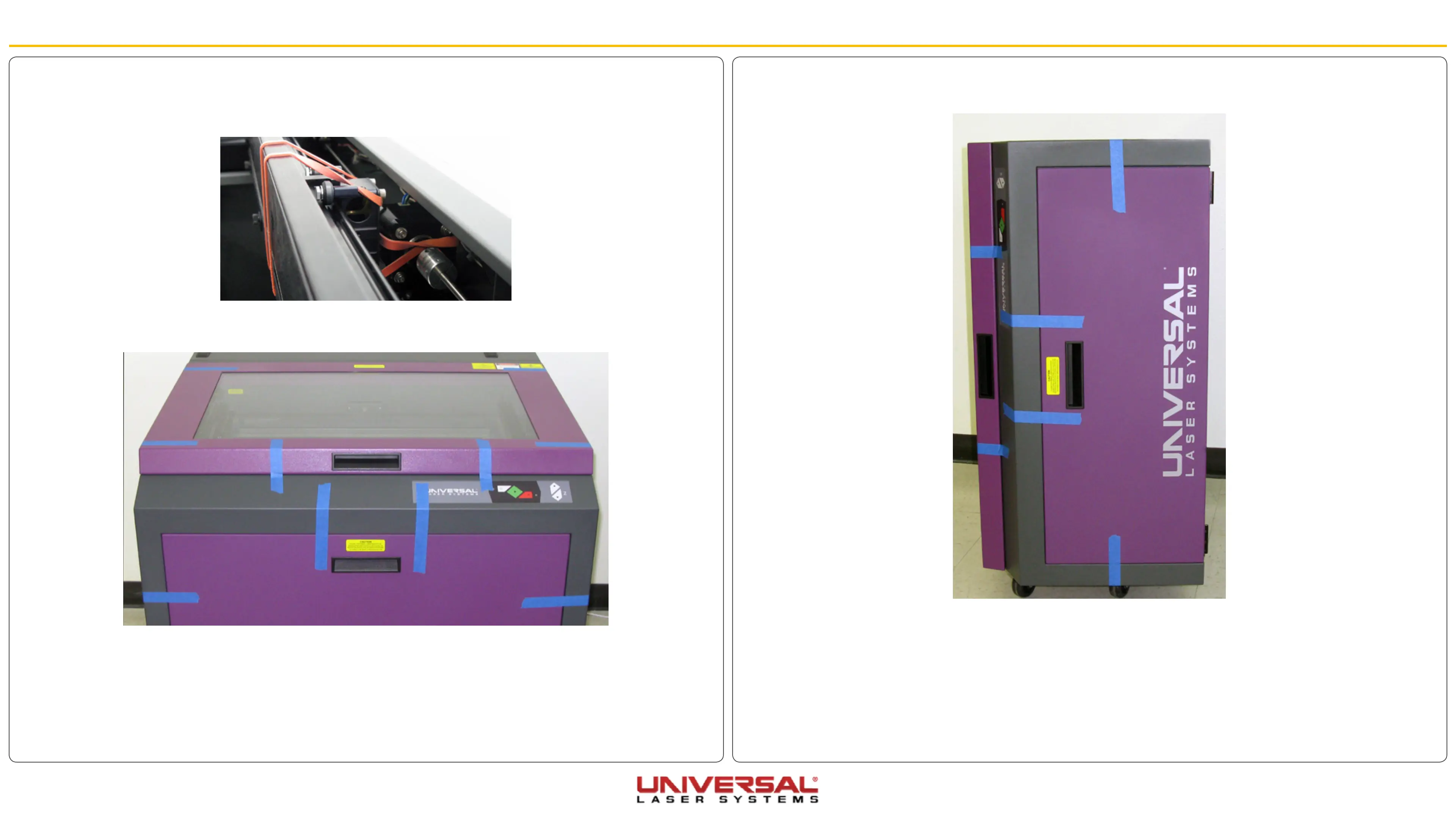
2. Using strong shipping tape or rope, secure the top and front doors so they do not open when the
system is tilted.
3. Remove the eight screws that attach the cart stand to the laser system, two per leg and four securing
the back panel to the bottom of the system, be careful with the washers that contain each screw as
these are very important for reassembly.