VLS Service Manual - REV2015.04
Table of Contents
Component Removal and Replacement
Page | 46
Component Removal and Replacement
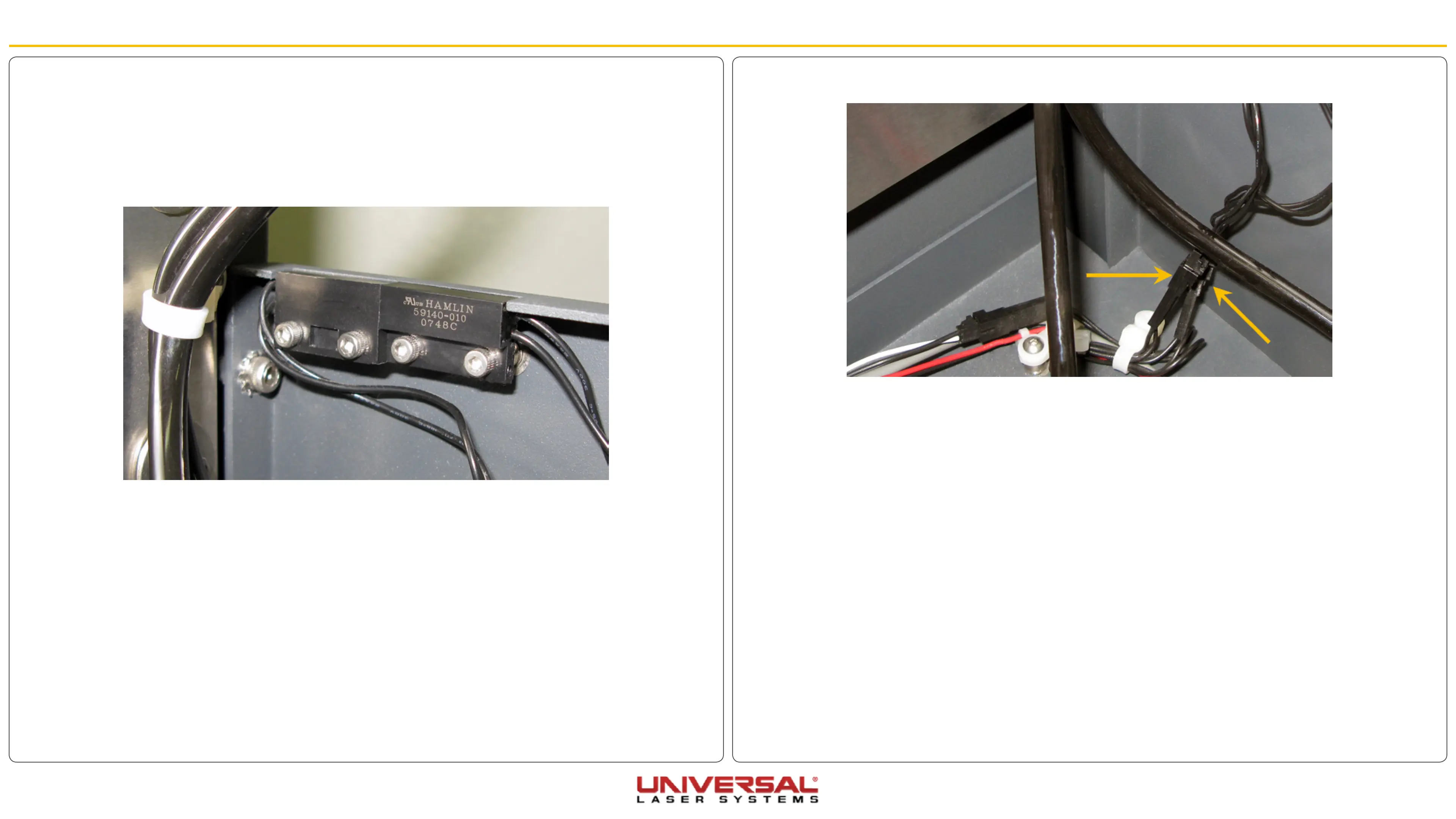
4. Disconnect the interlocks from the wiring harness.
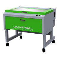
5. Remove the two screws holding the interlocks in position.
6. Installation is opposite of removal. Ensure the sensor is flush with the frame of the system.
7. Plug in and power ON the VLS. Open and close the rear cover. Check to see if the door open light on
the keypad turns on and off (red flashing light) when you open and close the cover. Or check the UCP to
see if the system is indicating that a door is open.
8. If adjustment is necessary loosen the two screws holding the interlock in position and slide the sensor
in or out. Retighten the screws and repeat Step 7 until complete.
Rear Cover Interlocks
1. Turn the VLS OFF and unplug the system.
2. Open the rear cover to its resting position.
3. Locate the two interlocks on the right-hand side (VLS3.60 & 4.60) or the left-hand side (VLS6.60) of the
system frame.