VLS Service Manual - REV2015.04
Table of Contents
X-Axis
Page | 51
X-Axis
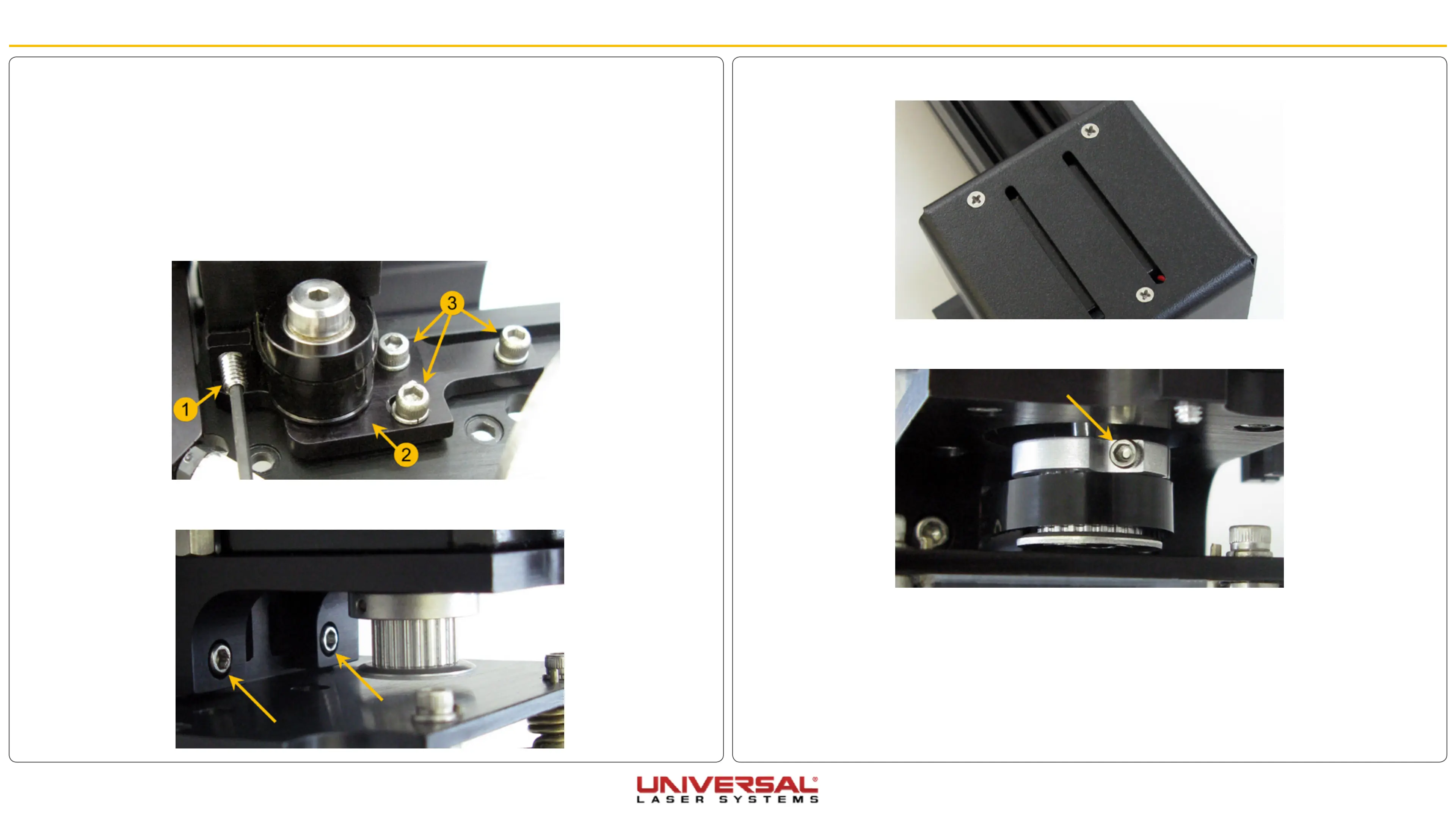
5. Remove the three screws on top of the X-axis Motor Cover and place them aside with the cover.
6. Remove the drive gear by loosening the screw on the retaining clamp, notice its position on the motor
shaft as it is not completely flush to it and it does not touch the motor.
7. If you are replacing the X-axis Motor continue to step 11, if not continue to the next step.
8. Position the new Drive Gear on the motor shaft so that it is in approximately the same position as the
old one. There should be a gap between the motor and the retaining clamp and the retaining clamp and
drive gear should be flush with each other.
9. Once the gear and retaining clamp are in place. Tighten the screw.
10. Installation is opposite to removal, once finished tension the belt according to the steps outlined in
X-Axis Belt Replacement.
X-Axis Motor and Drive Gear
X-Axis Drive Gear
1. Power OFF and unplug the VLS.
2. Remove the X-axis Arm and place it on a flat working surface by following the instructions in X-Axis Arm
Replacement.
3. Loosen the three screws (3) (1/2 turn) that mount the tensioning bracket (2). Also, back off the setscrew
(1) until the tip does not make contact (this will partially release the tension on the belt) but do not
remove the screw completely.
4. On the right end of the arm remove the two screws and the two washers that attach the motor bracket
to the X-axis rail. Remove the motor assembly from the arm.


 To Next Page