NT217 C GB1 22 / 27
8-11: Additional adjustments possible using PC + Software only
The recommended values or states are entered by Ultraflux during testing before
delivery.
However, it may be necessary to modify them to adjust them to the site. If most of the
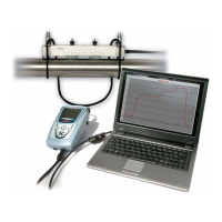
operations can be performed from the keyboard, some call for the LS_600W (be sure to
choose the right version). Using the software will also allow the backup of the modified
menu.
Parameter Menu Dialogue:
In addition to the fields already described, this menu will allow two text fields in order to
give MiniSonic an application or client name and an instrument reference, for instance: >
Cf. General sub-men, line 1 & Line 2
The MiniSonic internal clock time set is obtained by synchronizing it with that of the PC
being used: > Cf. General sub-menu, Synchronization with PC time = Yes
The software will allow a Delta To to be set to compensate for a zero default assumed to
be at zero flow and to prevent the Self-zero function from being launched. > Probe sub-
menu, Delta To
The software will allow the input of a Q max defining the scale of the Measurement
Dialogue menu graph. Using the scale of this Qmax, different from and independent of
the 4-20 mA scales parameterized elsewhere, it is possible to enter an erase flow rate
(display set to zero) at the bottom end of the scale: > Cf. Flow rate sub-men, Q rms. = %
Q max
As long as they are accepted, and therefore as long as rights are justified and authorized
by a confidential code, it is possible to work in a “Works Adjustment” menu. Contact
Ultraflux while justifying your request.
Works Adjustment Menu Dialogue:
This menu will allow determining fields to be modified for the application and which we
reserve for authorized people who have gone through in-depth training.
For information, we list some of the functions:
- Possible input of a Linearization curve, to compensate for an error curve characterized
by metrological tests. This curve is symmetrical to the error curve and entered by 11
points defining 10 segments per 10% section through to a “reference” flow rate at the
end of the scale. The input of Q ref = 0 renders the curve inoperative.
- Definition of one or two special probes.
- Input by Delta T Filtering of a threshold to deactivate measurement filtering and obtain
the best “response time / measurement stability” tradeoff. In this way, MiniSonic will be
able to respond quickly when the pump is started or after the opening of a solenoid
valve, and will then present filtered and stable reading when the flow rate is established.
- The limitation of the amplification gain (Max. Gain) to avoid the acknowledgment of
noise under default conditions.
- Adjustment of External Probe Correction parameter which we may optimize for
measurements on multi-product conduits.
- Simulation Menu for testing.
 Loading...