‐8‐
3.3 Vacuum Tubing
(1) Clean inner surfaces of vacuum vessel, tubing and valve. Then, after eliminating water
moisture, small particle, dust or rust carefully, connect tube to the pump.
If evacuating small size powder or dust particle, vacuum pump may cause trouble.
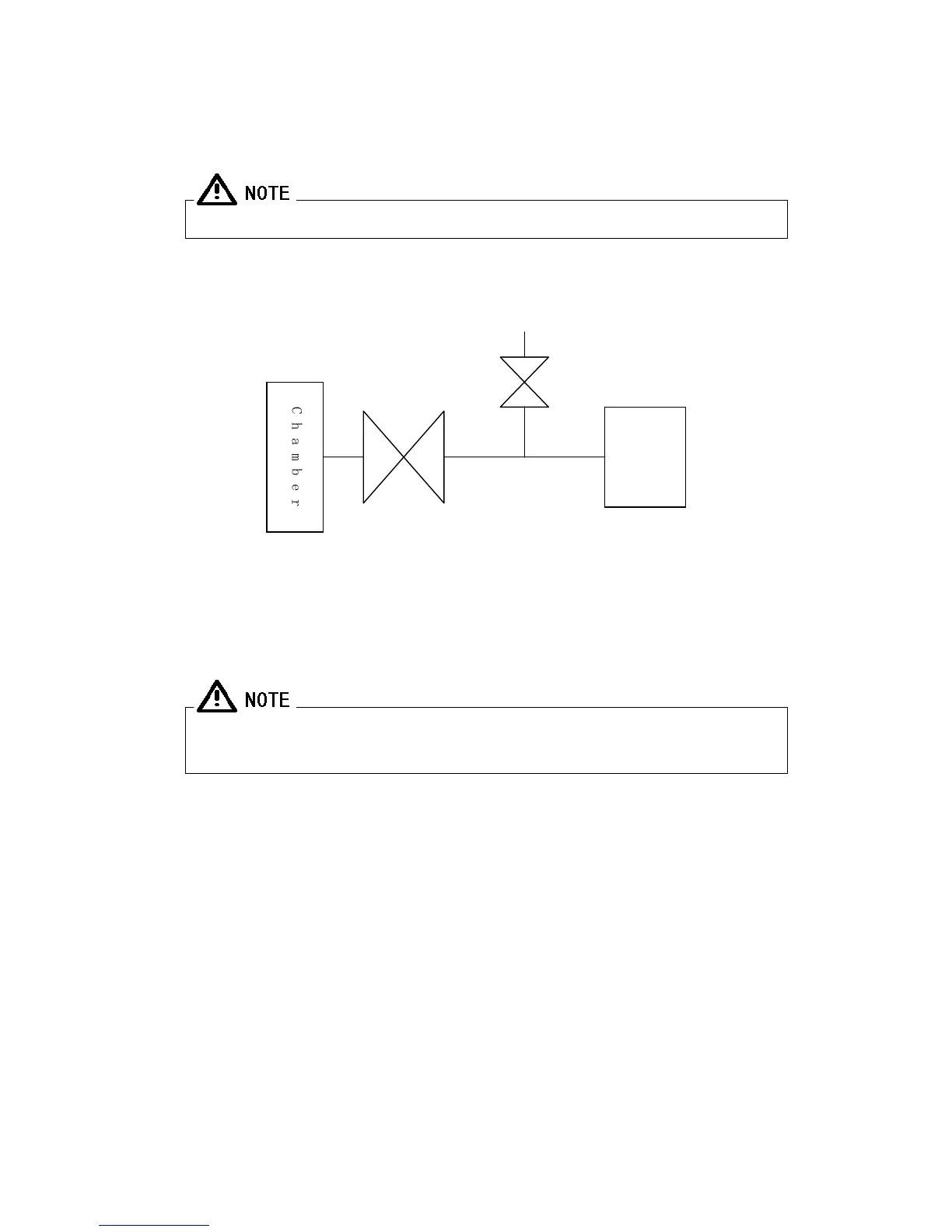
(2) Install the shut off valve (A) and the pump vent valve (B) in between the pump inlet port
and the vessel as shown in Fig-5.
Fig-5 Vacuum Pumping System Diagram
(3) Vacuum tubing between inlet port and another port is provided with vacuum rubber hose.
Do not eliminate mesh-filter for preventing different objects come into the inlet
port of the pump.
C
h
a
m
b
e
r
(A)
Shut off valve
Vent valve
(B)
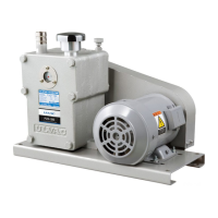
Pump