Doc. No: Unex-QSG-21-003
15/30
A printed version of this document is an uncontrolled copy
© 2023 Unex Technology Corporation – Company Confidential
Table 7: GNSS antenna status
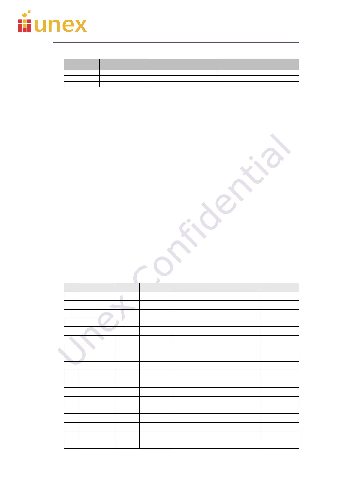
8.2. Mini PCIe Card Pinout
There are 3 groups of pins in the SOM-352 mPCIe pinout:
4 Group 1: Proprietary pins, originally marked as reserved in mPCIe standard
interface
5 Group 2: Standard mPCIe pins used by SOM-352, including 3.3 Vaux, ground,
PERST#, and USB data lines
6 Group 3: Standard mPCIe pins but not used in SOM-352, marked NC
SOM-352 only needs group1 and group2 pins for normal operation. For maximize
compatibility with existing mPCIe modules on the market, it is suggested to connect all
three groups of pins to the mPCIe connector.
Please note that the I/O directions listed here are on the SOM-352 side. For designing
a system board mPCIe interface, the input and output direction must be reversed.
Table 8: SOM-352 mini PCIe row 0 pinout
 Loading...