Doc. No: Unex-QSG-21-003
18/30
A printed version of this document is an uncontrolled copy
© 2023 Unex Technology Corporation – Company Confidential
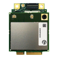
Figure 6: I/O Cable mating component P/N
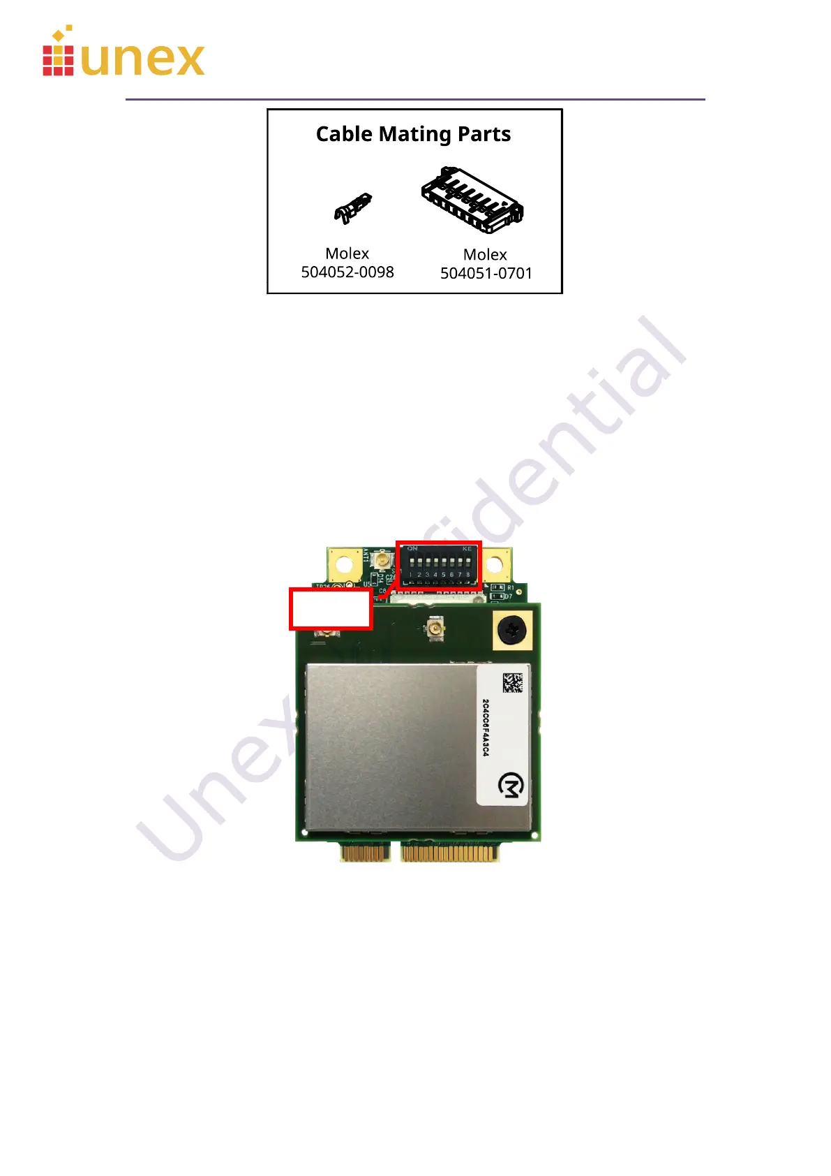
8.4. DIP Switch
The onboard DIP switch can help user to direct power and I/O signals from either
mPCIe interface or the I/O cable. The tamper signal trigger mode and firmware upgrade
can also be selected by user.
Figure 7: Onboard DIP switch
Please note that the in SW1.1 to SW1.6, the OFF position actually disconnects the
power/signal from the mPCIe pin, while the ON position ties mPCIe pins and I/O cable pins
together. In order to avoid interference and to keep 5V power from damaging your system
board, it is important to set the DIP switch to correct positions before connecting the I/O
cable.
 Loading...