EasyManua.ls Logo

UNI-T UT107 User Manual

UNI-T UT107
62 pages
To Next Page IconTo Next Page
Page #1 background imageLoading...
Page #1 background image
Table of Contents
Title Page
1
3
4
4
5
7
9
10
11
11
12
13
13
13
15
17
19
21
23
24
25
26
27
28
29
30
31
31
32
32
33
Model UT107: OPERATING MANUAL
Overview
Unpacking Inspection
Safety Information
Rules For Safe Operation
Automotive Servicing Safety Guide
International Electrical Symbols
The Meter Structure
Rotary Switch
Functional Buttons
Display Symbols
Measurement Operation
Part 1 Multimeter Basic Testing
A. DC Voltage Testing
B. AV Voltage Testing
C. DC Current Testing
D. Resistance Testing
E. Diode Testing
F. Continuity Testing
G. 12V Battery Measurement
H. Temperature Measurement
I. Frequency Measurement
J. Measuring Duty Cycle
K. Dwell Testing
L. Engine Tach (Rotation Speed)
Testing “RPMx10”
M. Operation of Hold Mode
Part 2 Diagnosis of Automotive Troubles
A. Fuse Testing: Check the fuse to see if
it is blown out
B. Switch Testing: Check the switch to see
if it can work correctly
C. Solenoid or Relay Testing
D. Starting/Charging System Testing

Table of Contents

Question and Answer IconNeed help?

Do you have a question about the UNI-T UT107 and is the answer not in the manual?

UNI-T UT107 Specifications

General IconGeneral
DisplayLCD
Max Current10A
Resistance Measurement200Ω to 20MΩ
Battery9V
Continuity BuzzerYes
Diode TestYes
Transistor TestYes
Input Impedance for DC Voltage Measurement10MΩ
Tach (RPM)Yes
Dwell AngleYes
TypeDigital
Digits3.5
Frequency Measurement20kHz
Temperature Range-40°C to 1000°C
Sampling Rate3 times per second

Summary

Product Overview and Safety

Meter Introduction and Controls

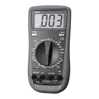
General introduction to the multimeter, its features, layout, controls, and display symbols.

Safety Precautions and Automotive Guidelines

Essential safety guidelines, warnings, and precautions for meter use and automotive servicing.

Unpacking, Symbols, and Meter Structure

Instructions for checking package contents and explanation of electrical symbols.

Basic Measurement Operations

Voltage and Current Measurements

Procedures for measuring DC voltage, AC voltage, and DC current with the multimeter.

Resistance, Diode, and Continuity Tests

Procedures for testing resistance, diodes, and checking electrical continuity.

Battery, Temperature, and Frequency

Procedures for measuring 12V battery voltage, temperature, and signal frequency.

Dwell, Tachometer, and Hold Mode

Procedures for measuring duty cycle, dwell angle, engine speed, and using hold mode.

Automotive Diagnostics and Sensor Testing

Circuit Component and System Testing

Procedures for testing automotive fuses, switches, solenoids, relays, and starting/charging systems.

Vehicle System Performance Tests

Tests for battery power consumption, load voltage, voltage drops, and charging system performance.

Ignition System Component Testing

Procedures for testing ignition coils, dampers, Hall sensors, magnetic sensors, and engine speed.

Fuel and Engine Sensor Diagnostics

Procedures for testing fuel system components and various engine sensors like O2, temp, position, MAP, and MAF.

Technical Specifications

General Meter Specifications

Overview of operating conditions, dimensions, safety compliance, and display features.

Measurement Accuracy and Ranges

Detailed accuracy, resolution, and overload protection for all measurement functions.

Maintenance and Service

General Service and Cleaning

Routine care, cleaning, and storage instructions.

Fuse and Battery Replacement

Step-by-step procedures for replacing fuses and the battery.

Related product manuals