EasyManuals Logo

UNI-T UT107 User Manual

UNI-T UT107
62 pages
To Next Page IconTo Next Page
To Previous Page IconTo Previous Page
Page #12 background image
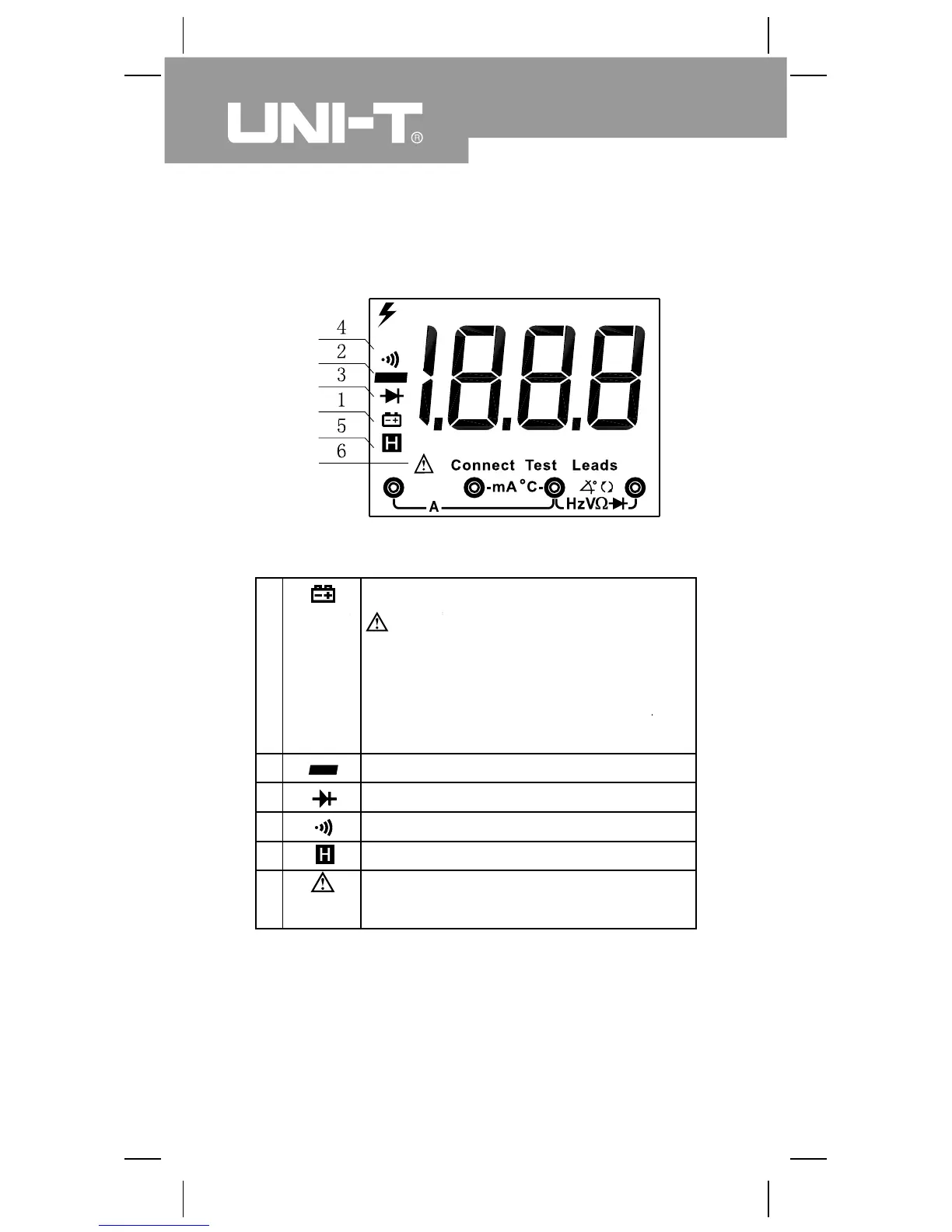
Display Symbols (see figure 2)
The battery is low.
Warning: To avoid false readings,
which could lead to possible electric
shock or personal injury, replace the
battery as soon as the battery indicator
appears.
Indicates negative reading.
Test of diode.
Continuity test.
Date hold is active.
Indicator of connecting test leads into
different input terminals.
( figure 2)
12
Model UT107: OPERATING MANUAL
1
2
3
4
5
6
Connect
test leads

Table of Contents

Questions and Answers:

Question and Answer IconNeed help?

Do you have a question about the UNI-T UT107 and is the answer not in the manual?

UNI-T UT107 Specifications

General IconGeneral
DisplayLCD
Max Current10A
Resistance Measurement200Ω to 20MΩ
Battery9V
Continuity BuzzerYes
Diode TestYes
Transistor TestYes
Input Impedance for DC Voltage Measurement10MΩ
Tach (RPM)Yes
Dwell AngleYes
TypeDigital
Digits3.5
Frequency Measurement20kHz
Temperature Range-40°C to 1000°C
Sampling Rate3 times per second

Related product manuals