Do you have a question about the Uniden GRANT and is the answer not in the manual?
Details FCC regulations for CB radios, prohibiting unauthorized alterations and specifying part replacement rules.
Explains the FCC's decision to remove licensing requirements for CB radio operators and its implications.
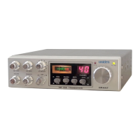
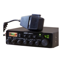
Provides guidance on selecting a location and securely mounting the transceiver in a vehicle.
Recommends quality antennas and discusses optimal mounting for whip antennas in automobiles and marine installations.
Explains how to identify negative and positive ground systems in vehicles for proper power connection.
Details the correct DC power cord connection for vehicles with a negative ground system.
Details the correct DC power cord connection for vehicles with a positive ground system.
Explains the requirements for operating the transceiver from a home or office using a separate power supply.
Step-by-step instructions for setting up the transceiver to receive signals, including squelch and clarifier adjustment.
Outlines the procedure for transmitting, including safety precautions and microphone usage.
Explains how to turn the transceiver on/off and adjust the audio output level.
Details the function of the Squelch control for eliminating background noise and receiving weak signals.
Explains the PA function and its relation to the Squelch control for external speaker use.
Describes the function of the Mode Selector switch for choosing between AM, USB, and LSB operation.
Explains how to adjust microphone input sensitivity for optimal modulation during transmission.
Details the RF Gain control for optimizing reception in areas with strong signal strength.
Explains the Clarifier control's use for fine-tuning receiver frequency and reducing adjacent channel interference.
Details the Channel Selector knob for choosing transmission and reception channels, noting the special use of Channel 9.
Describes the TX/RX indicator, showing red for transmission and green for reception.
Identifies the female connector for attaching the transmission line cable (PL-259) to the transceiver.
Details the PA SP jack for connecting an external speaker for public address system use, with placement advice.
Explains the External Speaker Jack for remote receiver monitoring, noting internal speaker disconnection.
Identifies the Power Jack for connecting the DC power cord supplied with the radio.
Lists general specifications including FCC type number, channels, frequency range, and input voltage.
Provides specifications for the transmitter, including power output, modulation, and signal suppression.
Details receiver specifications such as sensitivity, selectivity, cross modulation, and squelch threshold.
Lists specifications for the Public Address (PA) system, including power output and external speaker requirements.
Covers maintenance and adjustment procedures for the transceiver, emphasizing factory alignment.
Outlines periodic checks for preventive maintenance, including SWR, connections, and hardware tightness.
Explains that adjustment should only be done by a licensed technician using specific equipment.
Troubleshooting steps for a completely inoperative transceiver, focusing on power cord and fuse checks.
Troubleshooting steps for receiving problems, including volume, squelch, and operational mode checks.
Troubleshooting steps for transmitting problems, checking antenna connections and line integrity.
Outlines that UNIDEN warrants its CB Product to be free from defects in materials and craftsmanship.
Specifies that the warranty terminates two years after original purchase or if certain conditions are met.
Describes the remedy process, including repair, replacement, or refund for defective products.
Details the procedure for obtaining warranty service, requiring prepaid shipping and proof of purchase.
| Channels | 40 |
|---|---|
| Modes | AM/SSB |
| Power Output (AM) | 4 watts |
| Power Output (SSB) | 12 watts PEP |
| Modulation | AM/SSB |
| Antenna Impedance | 50 ohms |
| Power Supply | 13.8 V DC |
| Type | CB Transceiver |
| Frequency Range | 26.965 MHz to 27.405 MHz |