GENISYS II System Hardware Installation UNION SWITCH & SIGNAL
SM-6900B Rev. 0.0 August 1999 2-25
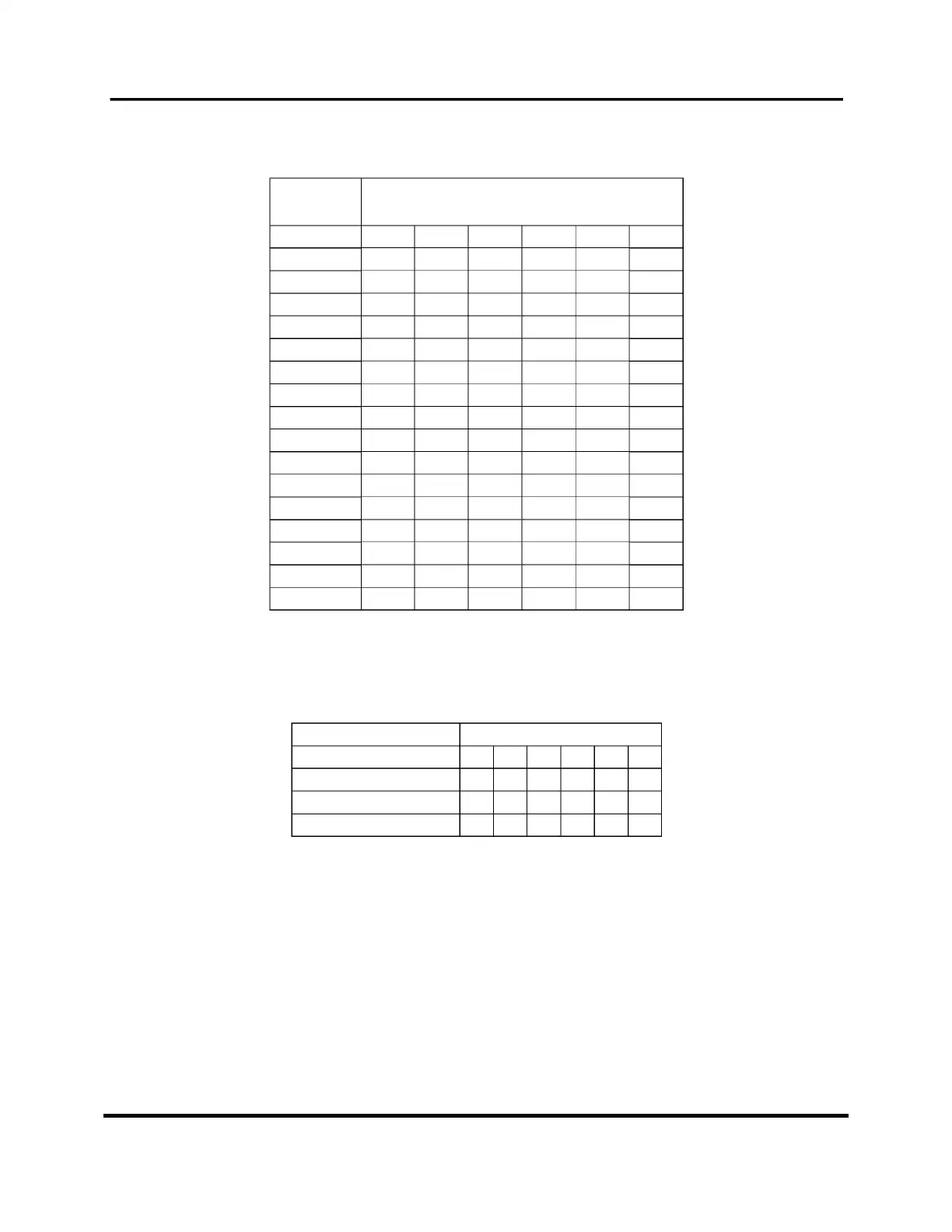
The following table shows how to set the jumpers for the GENISYS II I/O boards.
Note
: Each jumper may be set to either “0” or “1” position.
Board
Order
I/O Board
Jumpers
123456
1 000001
2 010001
3 001001
4 011001
5 000101
6 010101
7 001101
8 011101
9 000011
10 010011
11 001011
12 011011
13 000111
14 010111
15 001111
16 011111
For example, the first I/O board jumpers 1 through 5 are set to “0”, while jumper 6 is set to “1”.
The second I/O board will have jumpers 2 and 6 set to “1”, with the rest set at “0”, and so on.
As an example, the following list was formed using the table above:
Non-Lamp Boards Settings:
123456
NV_IN32_OUT16_1 0 0 0 0 0 1
NV_IN32_OUT16_2 0 1 0 0 0 1
NV_OUT32 0 0 1 0 0 1
It is assumed that the application software defines the boards as they are shown above, i.e., Board
#1 is the NV.IN32.OUT16 board, etc. It is the order in which they are defined in the application
program that determines the board number,
not
the relative position in the cardfile.
 Loading...