GENISYS II System Hardware Installation UNION SWITCH & SIGNAL
SM-6900B Rev. 0.0 August 1999 3-1
3. INSTALLING GENISYS II SYSTEM PERIPHERAL DEVICES
3.1 POWER-OFF RELAY INSTALLATION AND WIRING
The power-off relay is provided for GENISYS II installations that require the detection of
commercial power failure. A loss of commercial power drops the relay and closes a normally
open relay contact. The contact closure makes an input circuit to the non-vital I/O PCB in the
GENISYS II cardfile (see Figure 3-1).
The power-off relay is mounted on a plug-in base and secured with a spring clip. This base is
designed for attachment to a standard equipment rack DIN rail or can be secured to a flat surface
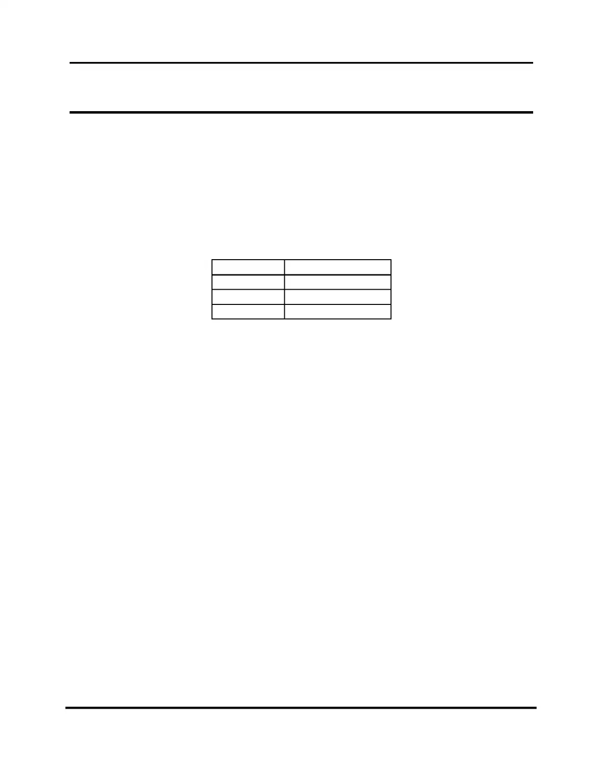
using a screw hole in the base under the relay. The part numbers are as follows:
Item US&S Part No.
Relay J726153-0283
Base J581782-0026
Spring clip J680167-0009
 Loading...