GENISYS II System Hardware Installation UNION SWITCH & SIGNAL
SM-6900B Rev. 0.0 August 1999 3-13
3.3 SERIAL COMMUNICATION ADAPTER PANEL
3.3.1 Installation and Power Input
The serial communications adapter panel (N451460-3001) is provided for GENISYS II serial
communications links that run between separate houses or cases. It incorporates the necessary
isolation and secondary protection circuitry to support serial communication between local signal
houses. This device consists of a 5-1/4 inch by 19-inch panel with a circuit board mounted on
standoffs. The panel is typically mounted in a standard 19-inch equipment rack. The following
hardware is required to mount the panel:
Item US&S Part No.
Nut J480203
Screw, #12-24 x 1/2 Pan Head J507261
Washer, #12 Shakeproof Lock J047750
The panel requires two power sources: a –12, +5 Vdc regulated power source that may be
provided by the connected GENISYS II unit and a 12 Vdc battery power source that drives the
20 mA current loops. Faston terminals are provided on the panel for power connections.
3.3.2 Interface Wiring
F
IGURE
3-2
shows a typical 20 mA current loop interface between master and slave GENISYS II
systems using the serial communications adapter panel. Transmit Data, Request-to-Send, Data
Carrier Detect, and Receive Data signals are each placed in a separate twisted pair with its
separate return wire. This is done to improve noise immunity from external sources and eliminate
possible cross talk between lines.
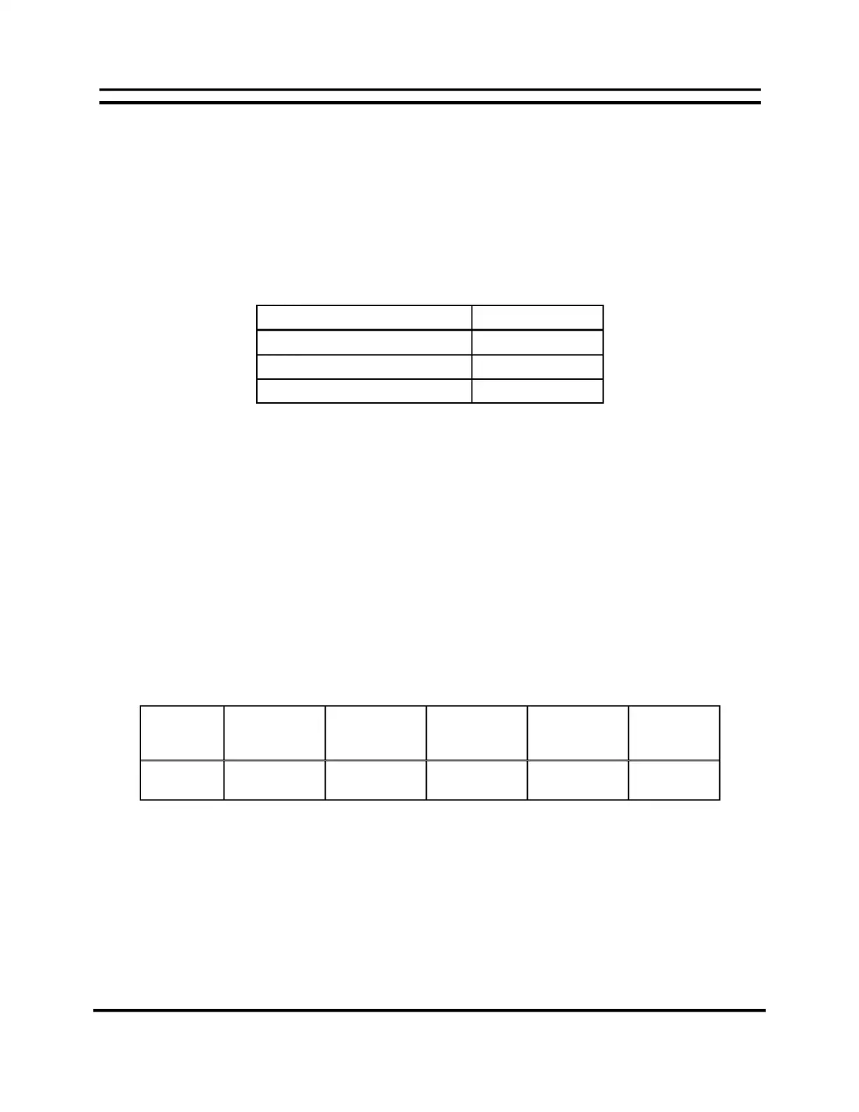
The current loop cable assembly is cut to length per the application and fitted with connectors.
The cable specifications are as follows:
Maximum
Cable
Length
Maximum
Total Cable
Path Length
Nominal
Cable Wire
Gauge/Type
Minimum
Cable Wire
Gauge/Type
Wire
Capacitance
Wire
Resistance
5,000 ft. 10,000 ft. #19 AWG
twisted pair
#24 AWG
twisted pair
>0.09 mF/
1000 ft.
>30 ohms/
mile
 Loading...