GENISYS II System Hardware Installation UNION SWITCH & SIGNAL
1-4 August 1999 SM-6900B Rev. 0.0
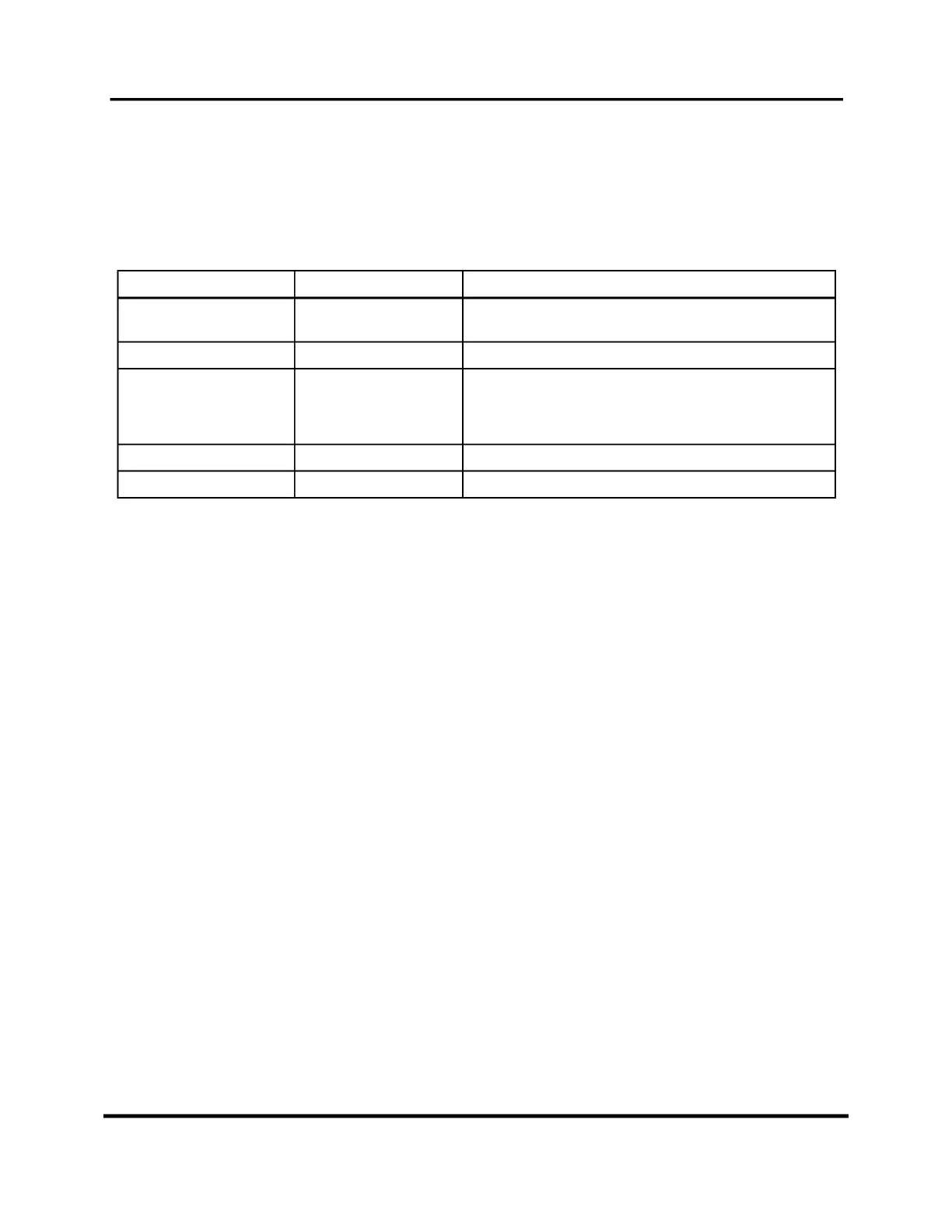
1.3.1 System Components
The GENISYS II control system is a non-vital logic emulator and remote control interface for
railroad and rail mass transit wayside interlocking installations. Table 1-1 lists the major
components of the GENISYS II system that are covered in this manual:
T
ABLE
1-1. GENISYS II S
YSTEM
M
AJOR
S
YSTEM
C
OMPONENTS
Name US&S Part No. Basic Function(s)
GENISYS II Cardfile N16902101 Houses all plug-in printed circuit boards and an optional local
control panel.
Power-Off Relay J726153-0283 Detects the failure of commercial power.
Serial Link Isolator Unit N16401101 Provides an “isolated common” interface between RS-232
compatible asynchronous serial communication ports on the
GENISYS II controller board and external communication
equipment.
Local Control Panel N17062901, N17062902 Optional built-in local control panels.
Installation Cables Contact US&S Eliminate the need for special wiring tools.
1.3.2 Cardfile and Plug-In Components
The GENISYS II cardfile is designed to house standard 6UX220 Eurocard plug-in printed circuit
boards. Most GENISYS II printed circuit boards are equipped with integral status indicator LEDs
on the board’s front panel.
In most applications, the cardfile will be equipped with a local control panel (LCP) that takes up
several cardfile slots. The LCP is interfaced to the cardfile circuitry and to the external inputs
through a dedicated non-vital I/O printed circuit board that occupies a cardfile slot directly
behind the LCP. Any unused slots in the cardfile are covered with blank shield panels. These
panels come in single slot and multi-slot widths. Each circuit board/panel is attached to the
cardfile frame with slotted-head machine screws. Two extraction levers are provided on each
board to make board removal easier. The GENISYS II cardfile can be wall- or shelf-mounted and
can be easily installed in a standard 19” equipment rack.
External wiring is connected to each circuit board through a 48-pin or 96-pin connector. Each
connector attaches directly to the board’s upper-edge connector at the rear of the card file.
Connector housings for I/O circuit boards incorporate a DIP switch that is used to set the
electrical address for the associated circuit board. The CPU connector housing has an internal
EEPROM that is used to store site-specific configuration data. Even if the CPU board is
replaced, the configuration data remains intact within the CPU connector’s EEPROM.
The GENISYS II cardfile plug-in components covered in this manual are listed in Table 1-2. See
Service Manual SM-6900A for a detailed description of each circuit board type.
 Loading...