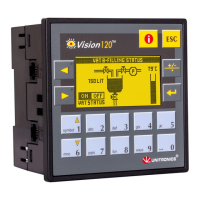
Voltage connection
Notes:
a. Shields should be connected at the signals source.
b. The 0V signal of the analog input must be connected to the controllers 0V.
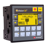
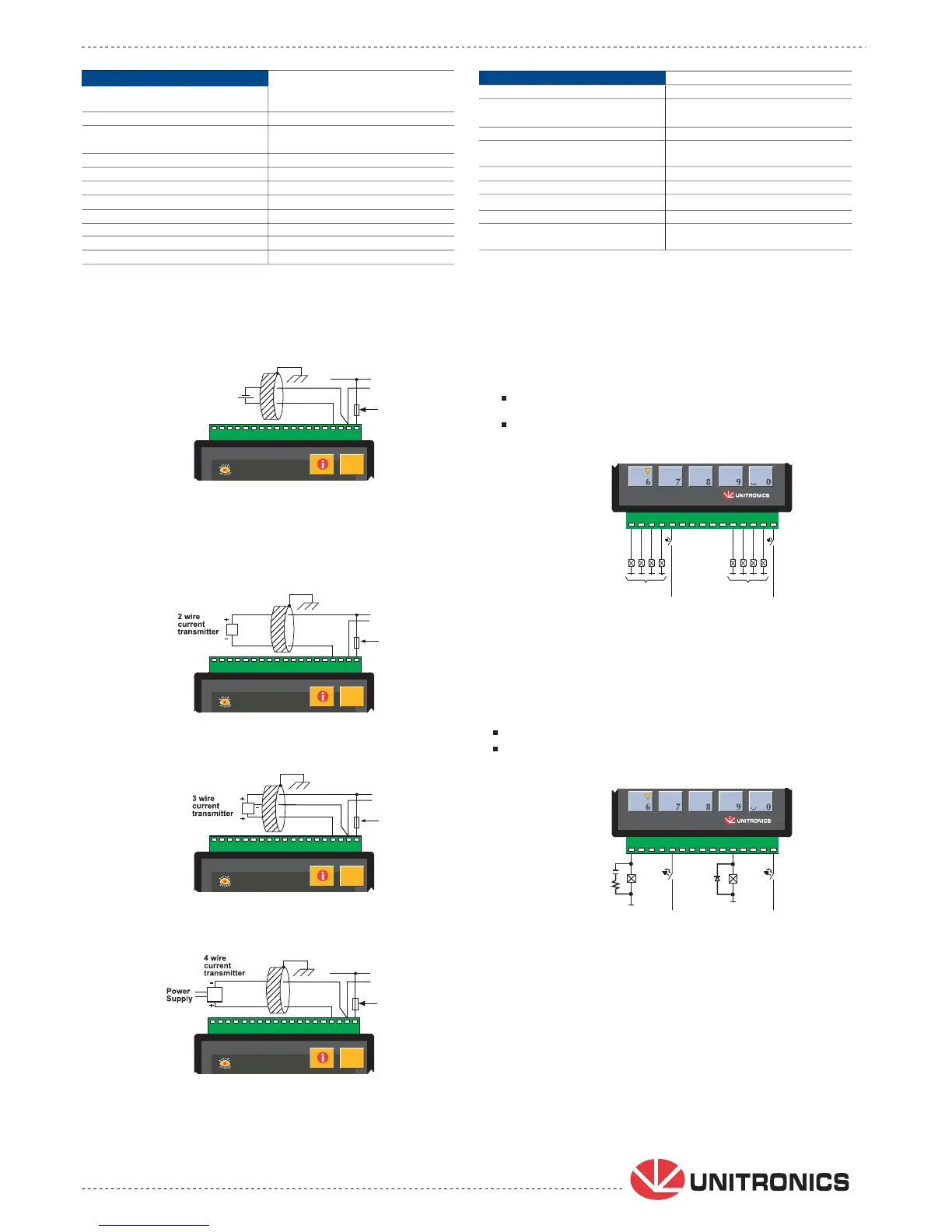
Current connections
Notes:
a. Shields should be connected at the signals source.
b. The 0V signal of the analog input must be connected to the controllers 0V.
+V
0V
24 VDC
Circuit
protection
device
0-10V
+
-
I1
I0
I3
I2
I4
I5
I6
I7
I8
I9
I10 I11
I12
I1
I0
I3
I2
I4
I5
I6
I7
I8
I9
I10 I11
I12
I1
I0
I3
I2
I4
I5
I6
I7
I8
I9
I10 I11
I12
I1
I0
I3
I2
I4
I5
I6
I7
I8
I9
I10 I11
I12
Note:
Outputs #0, #1, #2 and #3 share a common signal.
Outputs #4, #5, #6 and #7 share a common signal.
Outputs #8, #9, #10 and #11 share a common signal.
24 VDC
+V
0V
Circuit
protection
device
24 VDC
+V
0V
Circuit
protection
device
24 VDC
24 VDC
+V
0V
Circuit
protection
device
+V
0V
Circuit
protection
device
0V +V
0V +V
0V +V
0V +V
L1, L2, L3
(110/220VAC)
N
0V
N
L1, L2, L3
(110/220VAC)
®
Analog Inputs Two 10-bit, multi-range inputs:
0-10V, 0-20mA, 4-20mA
See Note 1 on page 1
Conversion method Successive approximation
Input impedance >150K
W for voltage
243
W for current
Galvanic isolation None
Resolution (except 4-20mA) 10-bit (1024 units)
Resolution at 4-20mA 204 to 1023 (820 units)
Conversion time Synchronized to scan time
Absolute max. rating ±15V/30mA
Full scale error ± 2 LSB
Linearity error ± 2 LSB
Status indication Yes, See Note
Note:
The analog value can also indicate when the input is functioning out of range.
If an analog input deviates above the permissible range, its value will be 1024.
2
Relay outputs
12 relay (in 3 groups) See Note
Output type SPST-NO (Form A)
Type of relay Tyco PCN-124D3MHZ
or compatible
Isolation by relay
Output current (resistive load) 3A max per output
8A max total for common
Rate voltage 250VAC / 30VDC
Minimum load 1mA@5VDC
Life expectancy 100k operations at maximum load
Response time 10mS (typical)
Contact protection External precautions required
(see below)
V120-22-R34 06/09
Relay Outputs
+V
24VDC
+V
24VDC
120
TM
mno
pqrs
tuv
wxyz
0V
AN0
AN1
AN0
AN1
AN0
AN1
AN0
AN1
Increasing Contact Life Span
To increase the life span of the relay output contacts
and protect the device from potential damage by
reverse EMF, connect:
a clamping diode in parallel to each inductive DC load.
an RC snubber circuit in parallel with each inductive AC load.
Each Output can be wired separately
to either AC or DC as shown below.
The 0V signal of the relay outputs is isolated
from the controllers 0V signal.