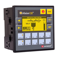
In this figure, the jumper settings will cause
the controller to function as follows:
Digital inputs: npn, 24VDC inputs
Analog input 1: Voltage input
Analog input 0: Current input
®
4
The tables below show how to set a specific jumper to change the functionality of the controller.
To open the controller and access the jumpers, refer to the directions at the end of these specifications.
Important:
Incompatible jumper settings and wiring connections may severely damage the controller.
Jumper #
NPN PNP*
Jumper #
Voltage Current Digital*
JP1 A A B
Digital Inputs
JP3 A B
Analog 1 / I14
JP4 A B B
JP2 A A B
Analog 0 / I15
JP5 A B B
V120-22-R34
I/O Jumper Setting
5410-1231-9
V120-22-R34 06/09
*Default factory setting
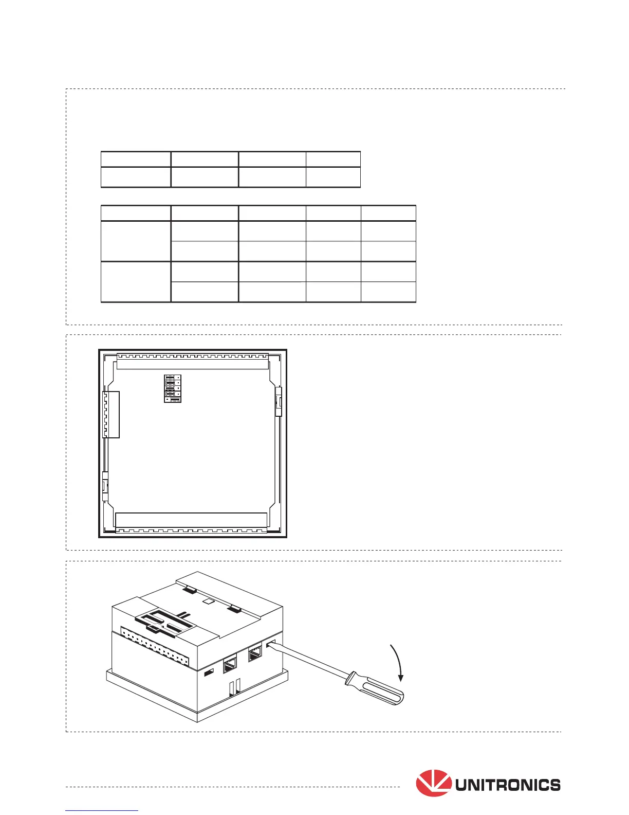
Opening the controller enclosure
1. Locate the 4 slots on the sides of the enclosure
2. Using the blade of a flat-bladed screwdriver, gently pry off the
back of the controller as shown in the figure below, exposing the
controller's board.
Unitronics reserves the right to revise this publication from time to time and to
amend its contents and related hardware and software at any time.
Technical updates (if any) may be included in subsequent editions (if any).
Unitronics product sold hereunder can be used with certain products of other
manufacturers at the users sole responsibility.
A B
1
2
3
4
5