Rear Panel
__________________________________________________________
- 7 -
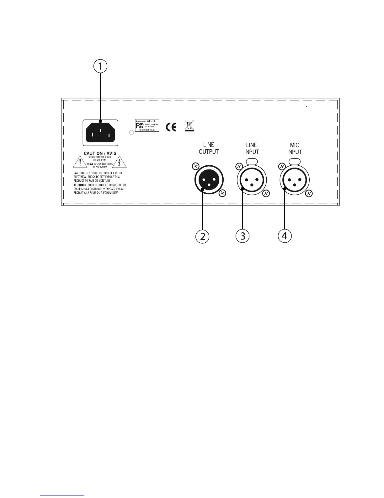
(1) AC Power Connector - Connect a standard, detachable IEC power cable (supplied) here.
(2) LINE OUTPUT - A balanced XLR connector that carries the line-level output signal of the 710. Note
that Pin 2 is positive when the front panel Polarity switch is off (INø). Pin 3 is positive when the front
panel Polarity switch is engaged (OUTø). ( see #11 on page 6)
(3) LINE INPUT - Connect a line-level input signal (coming from a device such as a mixer, DAW, tape
machine, or signal processor) into this balanced XLR connector. Pin 2 is wired positive (hot).
(4) MIC INPUT - Connect a microphone to this standard XLR connector. Pin 2 is wired positive (hot).
710 Twin-Finity
UNIVERSAL AUDIO, INC • SCOTTS VALLEY, CALIF. USA
POWER 100-240VAC 0.60A 50/60Hz