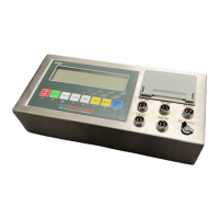
The US-M5 Indicator is a portable static weighing indicator designed for use with static axle scales. It offers both gross weighing and accumulative weighing modes, making it suitable for various weighing applications. The device features an LCD display measuring 5.3 inches by 1.4 inches, providing clear visibility of readings.
Function Description:
The US-M5 Indicator performs essential weighing functions including Tare, Zero, Print, Save, Check, and Delete. It supports both kilogram (kg) and pound (lb) weighing units, allowing for flexible use in different regions or for specific requirements. The indicator can connect to a secondary large display or scoreboard, enhancing visibility in larger settings. It is capable of connecting with up to four weighing pads, and it can display the individual scale/pad percentage of the total weight, which is useful for weight distribution analysis. The device supports both manual and automatic printing modes, and the date and time can be easily set. For data logging, it can connect to a PC or an external printer. Optional wireless capability further enhances its versatility. The keyboard and display are splash-proof, adding to its durability in various working environments.
Important Technical Specifications:
- Sensitivity: 0.5µV/d
- Input Voltage: -30 to +30mV DC
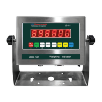
- Accuracy Class: III
- Initial Zero Range: ±10% Max
- Manually Zero Range: ±2% Max
- Zero Range: 100% Max
- Zero Tracking: 0.5d/s
- Excitation Circuit: VDC, 6-wire connection, capable of connecting a maximum of 24 load cells of 350Ω.
- AC Power: AC 100-250VAC, 50/60HZ (requires the supplied 9V adapter).
- Operation Temperature: -10°C ~ +40°C
- Operation Humidity: ≤90%RH
- Storage Temperature: -10°C ~ +40°C
- Battery: 6V/4.5Ah rechargeable battery.
- Adapter: 9V/1.2A adapter.
- Dimensions: 11.75 inches (width) x 5.5 inches (height).
Usage Features:
The US-M5 Indicator is designed for user-friendly operation.
- Power On/Off: Press and hold the power button for 2 seconds. The scale will flash the voltage and then perform an auto-check and count down from 0-9 before entering weighing mode. Any weight on the scale before powering on will be automatically tared out.
- Zeroing: The ZERO key resets the scale to 0 when empty. The manual zero range parameter allows for zeroing within a set selection; exceeding this range will result in an error, requiring a tare operation.
- Unit Selection: The KG/LB key switches between kilogram and pound units.
- Tare Function: The TARE key tares the current weight on the scale, entering net mode. Pressing it again exits tare mode and returns to gross mode. A pre-set tare weight can be input by holding the TARE key for 2 seconds, using arrow keys to enter the value, and pressing PRINT to confirm.
- Check Function: The CHECK key allows users to review previously saved weights. In weighing mode, pressing CHECK displays the number of saved records (e.g., "C 0030"). Users can input a specific record number (e.g., "C 0020") and press PRINT to view it. The display will show date, time, axle, tare weight, and total weight sequentially. Users can then choose to print this record.
- Switch Function: This function toggles the display between the total weight and the weight of each individual pad/scale. When displaying individual pads, it also shows the percentage of that pad's load relative to the total weight.
- Print Function: When the weight on the scale is stable, pressing the PRINT key will print the current weight.
- Calibration Procedure: The calibration process involves entering the indicator settings mode by holding SWITCH and PRINT keys. Users select the F2 settings mode, then choose the scale/pad to calibrate (1-4). After setting the span (CAL-1), with no load, press PRINT to zero calibrate. Then, set the span weight (SPAN-1) using arrow keys, load the calibration weight (at least 40% of capacity), and press PRINT when stable. Finally, save the calibration (SAVE-1) and exit.
- Parameter Settings: The indicator offers five setting modes (F1-F5) to adjust various parameters, including working mode, unit, decimal, graduation, capacity, axle number, cargo number, printing format, printing method, printing coupon numbers, baud rate, communication settings, automatic power off, backlight, date format, date, time, records storage, PCB version, software version, and ad codes for LFW, RFW, LRW, RRW. It also allows for deleting weighing records and all records.
- Weighing/Printing Modes:
- Normal Weighing Mode: Set Printing Format to "1" in F3 menu. Supports 1-4 pads. Example for 3 pads: connect to LFW, LRW, RRW interfaces. Drive the plane onto the pads. Use SWITCH to view total weight or individual pad weights and percentages. If Printing Method (PM) is "1" (automatic), printing and saving occur automatically when stable. If PM is "0" (manual), press PRINT to print results.
- Accumulative Weighing Mode: Set Printing Format to "2" in F3 menu. Supports 2 or 4 pads. Printing Method (PM) must be "0" (manual). Drive axle onto pads, press STORE to accumulate and print axle data. Repeat for all axles. Press PRINT to accumulate and print the total weight.
Maintenance Features:
- Battery Management: The indicator comes with a rechargeable battery. It is crucial to fully charge the internal battery before first use to prevent low voltage. If the battery is not used for an extended period, remove it to avoid leakage. To maintain battery health, fully discharge it monthly by leaving the indicator on until it powers off, then recharge fully. The battery charge is indicated by a symbol on the display; a flashing symbol indicates the battery needs charging.
- Printer Maintenance: The built-in needle printer requires occasional maintenance.
- Removing Lid: Press the lower corner tabs and squeeze while pulling outwards.
- Replacing Ink: Remove the lid, squeeze and pull the printer forward by its tabs. Hold the ink cartridge on both sides and pull straight down to remove. To replace, feed paper through the new ink cartridge, align the small holes on the cartridge with the gears under the left pull tab, push the cartridge upwards, and push the printer backward into the indicator. Replace the lid.
- Replacing Paper: Remove the lid, squeeze and pull the printer forward. Carefully remove the ink cartridge. If the paper roll is not empty, use the feed button to empty it. Squeeze both sides of the roll holder and pull forward to remove the old roll. Replace with a new paper roll, squeeze the roll holder back into the printer. Feed paper into the paper slot while holding the feed button, then feed paper into the ink cartridge. Push the cartridge upwards and push the printer backward into the indicator. Replace the lid.
- Troubleshooting: The manual provides an extensive list of error codes (e.g., "UUUUUUU" for overload, "Err 1" for weight above max capacity, "Err 5" for EEPROM Error) with corresponding reasons and solutions, facilitating self-diagnosis and resolution of common issues. Solutions range from reducing weight and checking connections to recalibration and PCB replacement.
- Anti-static Prevention: The indicator is static-sensitive equipment. Power should be cut off during electrical connections. Touching internal components by hand is prohibited. Operators should discharge any accumulated static charge before opening the protective container, ideally by wearing a grounded anti-static wrist strap and using an anti-static mat. Static electricity can influence weighing, so discharging static electricity from samples or wiping the pan and case with an anti-static agent is recommended.