IM 25.000AA UA (B/6-00)
CHLORINE HANDLING MANUAL
PAGE 4
Weight, Liquid
1 cf = 91.56 lb at 32° F.
Solubility in Water*
6.93 lbs./100 gals at 60° F and 1 atm.
Pressure vs Temperature
See Figure 1
*
NOTE: Theoretical values shown. Actual solubility in
water based on chlorinator performance has proven to be
3500 ppm or 2.92 lbs/100 gals maximum.
Chlorine is an oxidizing agent and will support combustion
but is not explosive or flammable. Many organic chemicals
will react with chlorine, some violently. Steel will ignite
spontaneously in the presence of chlorine at 483° F.
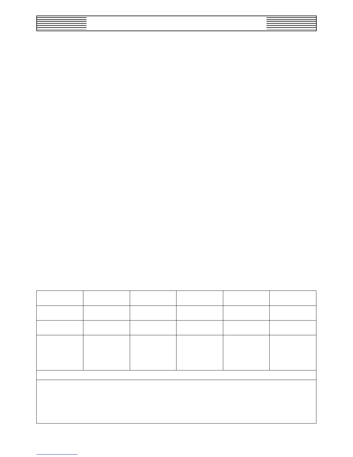
3 SUPPLY CONTAINERS
Table 1 gives details on the supply containers most com-
monly used with USF/W&T equipment.
Some large installations that would normally use single unit
tank cars but are not serviced by railroad facilities use tank
motor vehicles (tank trailers) which usually range in capacity
from 15 to 22 tons.
All supply containers must conform to appropriate Depart-
ment of Transportation (DOT) and Canadian Transport
Commission (CTC) regulations. It is the responsibility of the
supply container manufacturer and the chlorine supplier to
meet these requirements.
3.1 RATES
In general, using a remote vacuum type chlorinator, the maxi-
mum sustained gas withdrawal rate at which chlorine may be
taken from a 100 or 150 pound cylinder is one pound per day
per degree Fahrenheit (1.0 lb/24 hrs/°F). The corresponding
rate for ton containers is about 8.0 lbs/24 hrs/°F. At an as-
sumed liquid temperature of 70° F (and using a remote vacuum
type chlorinator) the above figures translate into 70 lbs/24
hrs for cylinders and 560 lbs/24 hrs for ton containers. For
a direct feed cylinder pressure operated chlorinator these
rates become 42 and 336 lbs/24 hrs respectively. These rates
can be increased substantially for brief periods. Do not place
containers in a water bath or apply direct heat in order to
permit higher withdrawal rates.
It is not practical to withdraw chlorine as a gas from tank cars
(or tank trailers).
3.1.1 MANIFOLDING FOR GAS WITHDRAWAL
When higher gas withdrawal rates are required, cylinders or
the gas valves (upper) of ton containers may be manifolded.
A typical arrangement for manifolding cylinders is shown in
Figure 2.
If cylinders or ton containers are manifolded, it is essential
that all supply containers be at the same temperature to pre-
vent the transfer of liquid chlorine from a warmer container
to a cooler container, possibly resulting in a container be-
coming overfilled through reliquefaction of chlorine in the
cooler container.
NOITAMROFNIRENIATNOCENIROLHC-1ELBAT
FOEPYT
RENIATNOC
THGIEWTENTHGIEWERATSSORG
THGIEW
EDISTUO
RETEMAID
HTGNEL
SREDNILYC bl001
bl051
bl511-36
bl041-58
bl512-361
bl092-532
"¾01-"¼8
"¾01-"¼01
"11'4-"½3'3
"8'4-"5'4
NOT
RENIATNOC
bl0002bl0561-0031bl0563-033"6'2"½01'6-"¾7'6
TINUELGNIS
SRACKNAT
snot61
snot03
snot55
snot58
snot09
-
-
-
-
-
-
-
-
-
-
"0'21-"5'01
"7'31-"½4'21
"1'51-"3'41
"1'51-"11'41
"1'51-"11'41
"3'33-"2'23
"½11'53-"01'33
"0'34-"9'92
"0'05-"7'34
"2'74-"8'54
.cnI,etutitsnIenirolhCehtybdehsilbup,noitidEhtfiF,launaMenirolhCmorfatadlanoisnemiD
aivytpmerollufdeppihsebyamezisbl051robl001ehtrehtiE.elbaliavaylidaertsomyllarenegsirednilycbl051ehT)1(
.sdaolracrokcurtllufnirostolllamsniliarrokcurt
ehtetanimileotredronidedeensaracehtmorfyltceriddedaolnuyllarenegsisraCknaTtinUelgniSmorfenirolhC)2(
owT.ylnosgnidisetavirpotdengisnoceradnadoirepsihtgnirudremusnocehtotdesaelerasraC.sknategarotsfoytissecen
nwod-tuhstuohtiwnoitareposuounitnoctimrepotdnasracfognildnahehtetatilicafotdednemmocereraskcartlellarap
.dehctiwsgnieberasracelihwsdoirep