IM 25.000AA UA (B/6-00)
CHLORINE HANDLING MANUAL
PAGE 10
encountered. Do not run these gas lines along exterior walls
that may be cold in winter months. Do not run pressure gas
lines under windows from which cold air descends in winter
months.
If the source of gas is one or more ton containers connected
to a manifold, install a drip leg of 1.0-inch schedule 80
seamless steel pipe approximately 18 inches long in a tee in
the manifold with the lower end capped. Locate the drip leg
immediately downstream of the last container connection to
intercept the liquid that comes from the ton containers’ gas
eduction tubes when initially opened.
Gas may be withdrawn from two or more containers simul-
taneously provided all containers are at the same tempera-
ture. Refer to Paragraph 3.1.
The installation of chlorine gas strainers in pipe lines up-
stream from pressure reducing valves or vacuum regulators
is a common practice. These strainers can also serve as traps
for a small amount of liquid chlorine. Figure 12 illustrates a
typical strainer.
Figure 12 – Chlorine Gas Strainer
HOUSING
GASKET
SCREEN
AND COVER
BOLT
4.3 LIQUID PIPING INSTALLATION REQUIRE-
MENTS
It is important to avoid conditions that will encourage vapor-
ization. Thus it is important to keep liquid chlorine lines as
cool as, or cooler than, the containers themselves by elimi-
nating restrictive fittings and always operating with fully
opened line valves. Avoid running liquid chlorine lines
through overheated areas where gasification is likely.
Valves in liquid chlorine lines should be kept to a minimum.
It is particularly important to avoid situations where it is easy
to close two valves in a line thus trapping liquid that, upon
an increase in temperature, will expand and develop higher
than acceptable pressures.
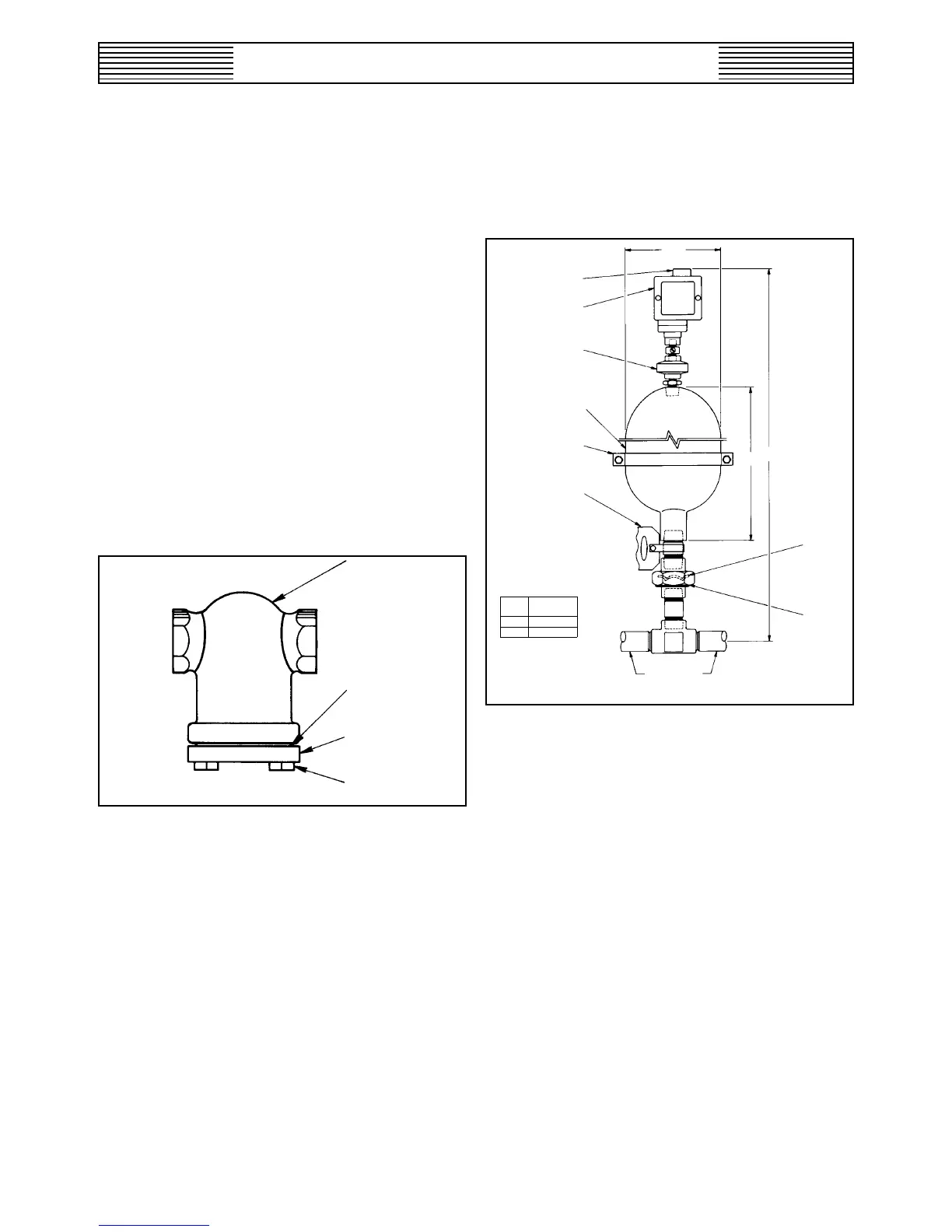
A liquid line pressure relief system (which includes a rupture
disc and an expansion chamber) is required where liquid
may be trapped in the line or where it is necessary to run lines
a considerable distance. The relief system is detailed in Fig-
ure 13.
Figure 13 – Liquid Line Pressure Relief System
6-5/8”
1/2” FEMALE NPT FOR
115 V ELECTRICAL
CONNECTION
PRESSURE
SWITCH
DIAPHRAGM SEAL
UNIT
EXPANSION
CHAMBER
SUPPORT BRACKET
WARNING LABEL
LENGTH OF LIQUID LINE
PROTECTED PER EXPANSION
CHAMBER SYSTEM
1” CHLORINE
LINE
UNION
HEAD
RUPTURE
DISC
46-1/4”
30”
EPIP
EZISENIROLHC
"1'573
"4/3'526
The expansion chamber provides an area for expansion in
the event that valves at both ends of the line are closed.
Relief system placement must be based not only on length
of line but also placement of valves.
4.4 PRESSURE RELIEF AND VENT PIPING RE-
QUIREMENTS
All pressure relief vent line systems must be treated as though
they contain chlorine. Use the same materials for pressure
relief vent lines as used for chlorine gas piping, unless the
vent line is a combination pressure relief/vacuum relief line
in which case the material must be suitable for moist chlorine
gas (PVC or polyethylene tubing).
Vent lines must be run in such a way that moisture collecting
traps are avoided. A continuous gradient is preferred. The
end of all vent lines must be turned down and screened.
Manifolding of vent lines is an acceptable practice provided
only like vents are manifolded (i.e., evaporator water vapor