CHLORINE HANDLING MANUAL
IM 25.000AA UA (B/6-00) PAGE 11
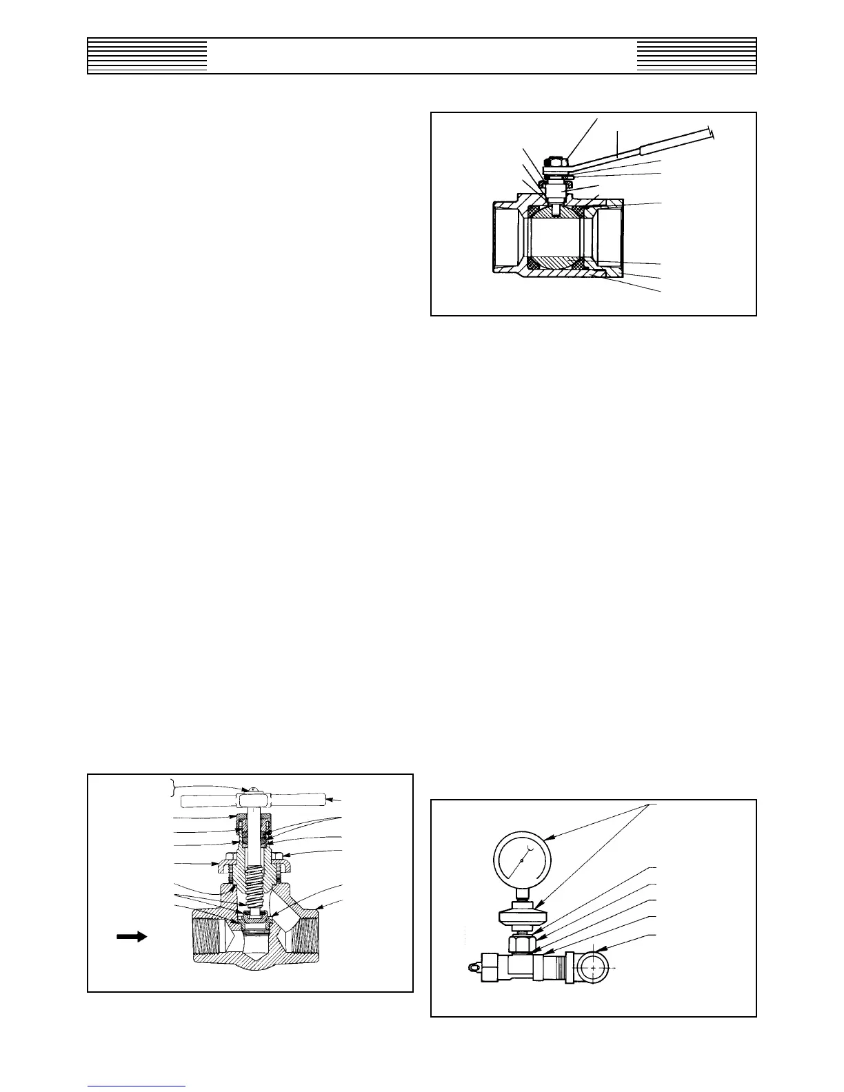
Figure 15 – Gas and Liquid Ball Valve
vents must be separate from gas pressure reducing valve
pressure vents, etc.). The interior cross sectioned area of a
common vent or pressure relief line should be approximately
equal to the sum of the cross sectional areas of the individual
vent lines.
WARNING: THE VENT LINE AND RELIEF LINE
MUST TERMINATE IN AN AREA GAS FUMES CAN-
NOT CAUSE INJURY TO PERSONNEL OR DAMAGE.
DO NOT TERMINATE THE VENT LINE AND RE-
LIEF LINE AT A LOCATION ROUTINELY USED BY
PERSONNEL, SUCH AS WORK AREAS OR PATH-
WAYS NOR NEAR ANY WINDOWS OR VENTILA-
TION SYSTEM INTAKES. IF AN AREA MEETING
THESE REQUIREMENTS IS NOT AVAILABLE,
REFER TO THE CHLORINE INSTITUTE’S CHLO-
RINE MANUAL AND PAMPHLET NO. 9 FOR AL-
TERNATE METHOD OF RELIEF DISPOSAL.
4.5 VALVES
Yoke type auxiliary cylinder, yoke type auxiliary ton con-
tainer, and header valves are described adequately in the
chlorinator or vacuum regulator instruction book.
Line valves are used to isolate alternate sources of supply
(manifolded banks of ton containers or tank cars), individual
evaporators or pressure type chlorinators. Sufficient line
valves should be provided for flexibility of system operation
consistent with the recommended practice of eliminating
redundant or unnecessary valves.
Valves are usually of approximately globe pattern as shown
in Figure 14 or ball type as shown in Figure 15.
Care should be taken that only valves designed by the manu-
facturer specifically for chlorine service are used. Ball valves
must include a provision for venting the cavity in the closed
position to the upstream side.
Figure 14 – 3/4- and 1-Inch Line Valves
MACH. SCREW
WASHER
PACKING NUT
PACKING GUARD
PACKING BOX
GAP
LEAD GASKET
STEM UNIT
LEAD GASKET
INLET
HANDLE
PACKING
PACKING RING
CAP SCREW (4)
SEAT
VALVE BODY
4.6 PRESSURE GAUGES AND SWITCHES
Whenever pressure gauges and switches are used in chlorine
liquid or gas lines, they must be of the type protected by a
flanged diaphragm seal specifically designed for chlorine ser-
vice to prevent the entry of chlorine into the gauge or switch
mechanism. The fill material must be suitable for chlorine
service. The connection between the seal and the gauge or
switch must not be broken. If the connection is inadvertently
broken, the complete assembly must be discarded and replaced,
unless it can be returned to the manufacturer for repair.
Frequently, valves are installed between chlorine lines and
the gauge or switch diaphragm seal to permit removal with-
out taking the line out of service. A means of relieving the
pressure in the isolated piping, gauge, or switch is strongly
recommended.
WARNING: RELEASING EVEN A SMALL AMOUNT
OF LIQUID CHLORINE IS DANGEROUS AND RE-
QUIRES EXTREME CAUTION TO AVOID SEVERE
PERSONAL INJURY. ALWAYS USE PROTECTIVE
EQUIPMENT WHEN RELIEVING PRESSURE, EVEN
IN ISOLATED CHLORINE GAS PIPING.
Since small size line valves for chlorine are not readily avail-
able, many times a header valve is used as shown in Figure 16.
Figure 16 – Chlorine Pressure Gauge or
Switch Mounted on Header Valve
PRESSURE GAUGE
(OR SWITCH) AND
DIAPHRAGM
UNION ADAPTER
UNION NUT
LEAD GASKET
HEADER VALVE
3/4” CONNECTION
IN GAS LINE
RETAINING RING
INDICATOR STOP
BODY SEAL
BALL
BODY CAP
BODY
STEM
SEAT
HANDLE
STEM NUT
BONNET PLATE
STEM BEARING
STEM SEAL