4c. Compact soener assembly
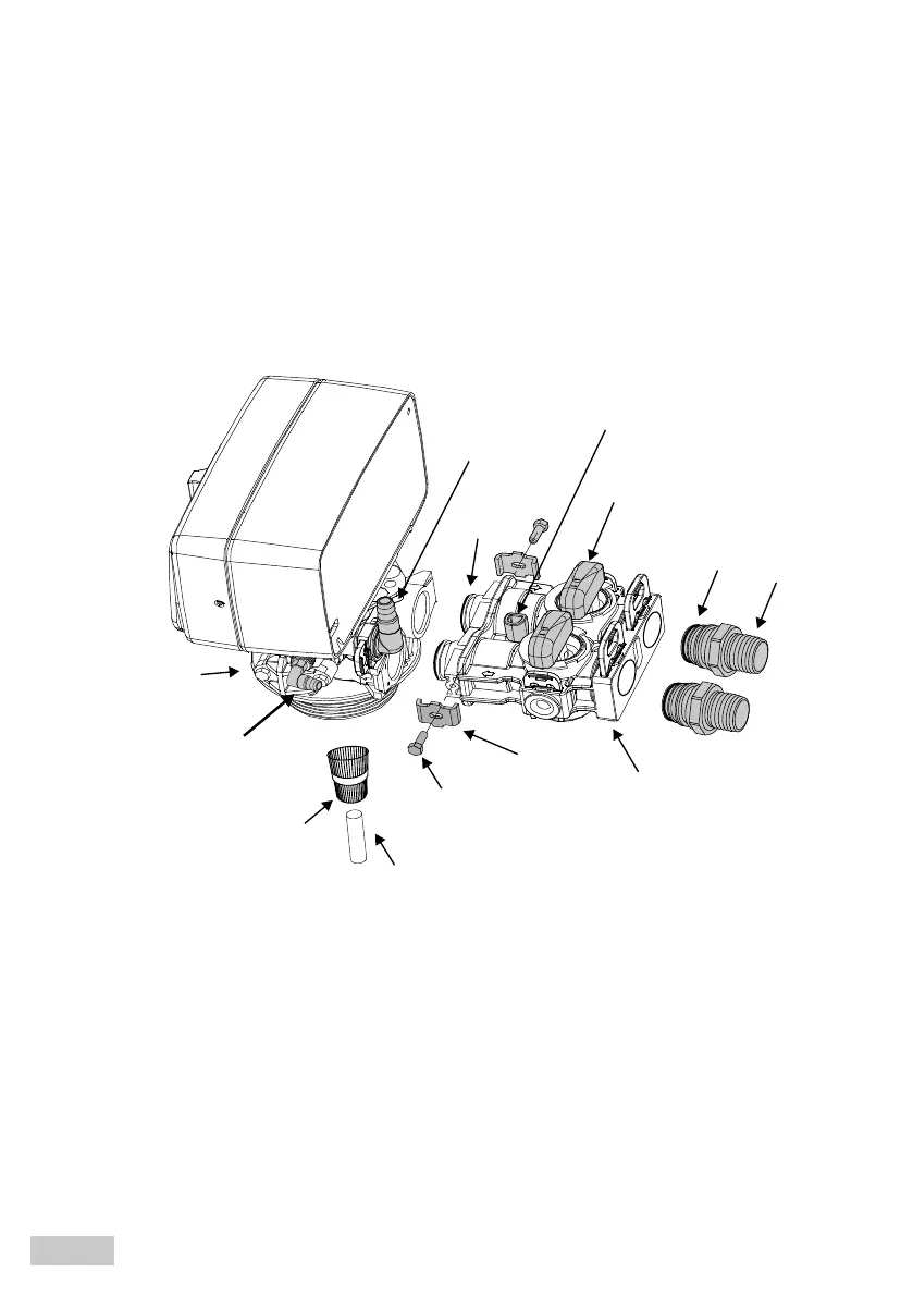
1. According to the figure below, attach the by-pass valve to the head using clamps and screws.
2. Lubricate the orings in the by-pass.
3. Connect the provided 1” connections to the system (aer the watermeter and/or hydrophore).
4. Connect the drain hose (not included) to the drain elbow.
5. Connect the overflow hose (not included) to the elbow on the casing.
If the overflow is installed in the sewage system, an air gap or siphon should be used.
Fig. 3. By-pass connection
control head
brine
elbow
fastener
By-pass valve
distribution pipe
By-pass valve
flow sensor socket
drain
elbow
1” connections
O-ring
O-ring
screw
upper
basket
EN
17