Chapter 3: Installation
Stratos EX Hazardous Area Aspirating Smoke Detection System Installation Manual 27
Power supply connections
The power supply cable should be of three-core screened type and should be led
through cable gland 1 or 2, leaving about 170 mm of the cable extending from
cable gland 1 or 100 mm from cable gland 2.
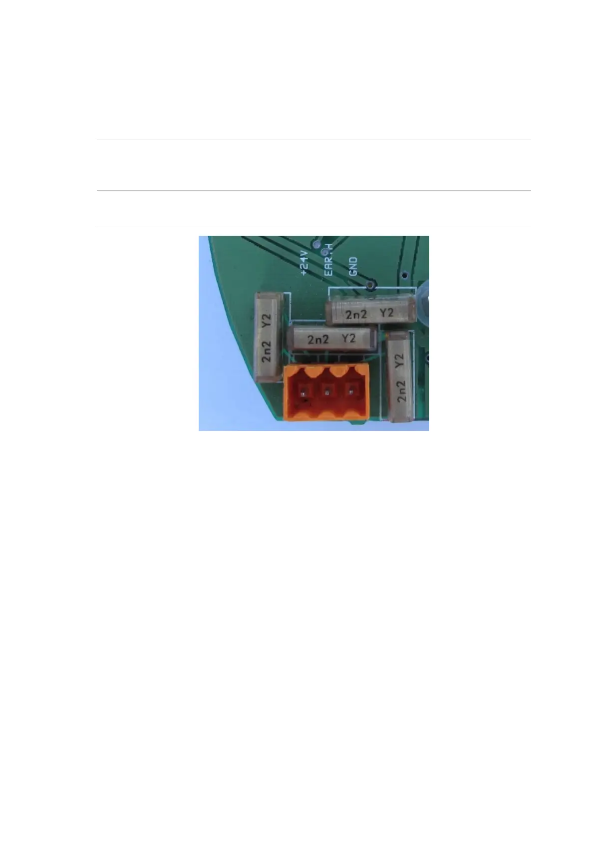
Caution: Note the orientation of the terminal block. Connect 0 V and +24 VDC to
the “0V” and “24V” screw terminals respectively. Connect the earth to the earth
terminal.
Figure 12: Power supply connection
Signal connections
Signal connections should be made using cable suitable for the hazardous area
and compatible cable glands. If RS-485 connection is used, the A+B signals
should ideally be taken through twisted pair cable. The SCN terminal should be
connected to the cable screen if possible; otherwise a third conductor should be
used.
Signals and power should not normally be in the same cable, as electrical noise
can jump between conductors.
 Loading...