Floor Screed Machine HD 50 17
www.utiform.com departamento.técnico@utiform.com Tfno. + 34 96 570 29 82 Fax: + 34 96 570 29 83
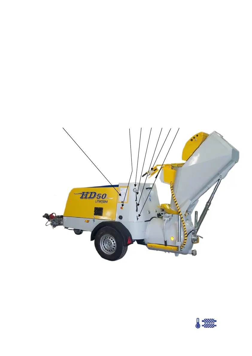
5 Service elements
1 Control panel
2 Pressure gauge
3 Ball valves
3a Vessel ball valves
3b Material outlet ball valves
4 Emergency switch
5 Hydraulic distributor level, hopper activator (according to model)
6 Radio frequency remote control, loading shovel activator (according to model)
1 4 2 3a 3b 6 5
5.1 Control Panel
The motor compressor has the requisite safety devices to guarantee correct operation, while guarding against
breakdowns produced by anomalous work situations.
In case of stoppage, failure is indicated in the instrument panel. Details of the safety devices are indicated
below:
5.1.1 Air pressure meter (PT)
Indicates work pressure of the unit. It is situated inside the machine on the gas-oil tank.